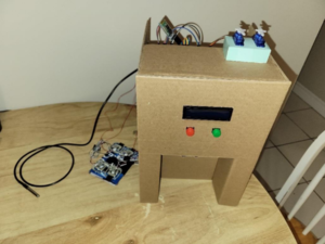
This project was completed and the findings were reported collaboratively by Jadyn Powell and Dilpreet Bhambra.
The purpose of this project was to design, test, and develop a circuit for an automated Coffee Barista using an Arduino Uno microcontroller board and a wide variety of sensors and actuators. The design had to include a minimum of four sensors and three actuators, and was to be completed within five weeks, excluding the initial ideation process. A Printed Circuit Board (PCB) was also designed, manufactured, and tested, to simplify the circuitry of the Coffee Barista. The Coffee Barista is an automated milk and sugar dispenser, with quantities that are specified by the user using pushbuttons and includes an LCD screen that displays the specified quantities. Two servo motors are used to dispense the milk/sugar. Once the amount of milk/sugar has been selected, the motors will be used to open their respective reservoirs for a specific amount of time based on the quantity selected. An ultrasonic sensor is used to detect the presence of a cup and will prevent any milk and/or sugar from being dispensed if there is no cup detected. The device also monitors the quantity of milk within the storage container using a weight sensor and alerts the user via a Bluetooth connection to their phone as to when the milk is running low. This same alert is displayed on the LCD screen and the servo motors are prohibited from turning, preventing any milk dispensing until the container is refilled. The temperature of the milk is also monitored using a temperature probe sensor, and another alert is sent to the user, via the same method, when the milk temperature rises above a safe storage level. Again, the same alert is displayed on the LCD screen and the servo motors are prohibited from turning, preventing the user from dispensing any milk that does not fall within the USDA standards for safe milk storage. After the five-week timeline, the circuit for the Coffee Barista was fully functional, all sensors and actuators operated as expected, and the designed PCB was printed and tested, and proved to be fully functional.
Introduction[edit | edit source]
Problem Definition[edit | edit source]
Many people rely on and look forward to starting their morning off with a fresh cup of hot coffee. However, it can be difficult to get the correct proportions of milk/sugar as per an individual’s preference and testing the coffee poses a risk of burning one’s mouth/tongue since the coffee is hot. By the time the coffee has cooled to a drinkable temperature, it may be too late to add additional milk/sugar. Creating a system to automatically dispense the correct proportions of milk/sugar which can be personalized to each person’s individual preferences will alleviate this issue and risk.
Aims and Objectives[edit | edit source]
The purpose of this project was to design, test, and develop a circuit for an automated Coffee Barista using an Arduino Uno microcontroller board and a wide variety of sensors and actuators. The design had to include a minimum of four sensors and three actuators, and was to be completed within five weeks, excluding the initial ideation process.
Literature Review[edit | edit source]
Developing a system which automatically dispenses the correct proportions of milk/sugar, which can be personalized to each person’s individual preferences, will alleviate the issue and risk of not being able to reliably get the correct proportions of milk/sugar and the risk of burning one’s mouth/tongue while testing hot coffee. There are pre-existing milk/sugar dispensers for coffee, such as the Newco Coffee Companion. These are intended for large scale, industrial use which does not solve the issue for users at home and in smaller locations. Since the storage size of the milk and sugar can be changed to fit individual needs, whether it is a much smaller scale for at home use, or much larger scale for use in a cafeteria, the Coffee Barista is able to reach a wide target audience. Many of the existing designs also do not have any way of ensuring no mess is made, other than a catch basin which the cup is placed on top of. The Coffee Barista is designed with an ultrasonic sensor, which will prevent any milk and/or sugar from being dispensed if there is no cup detected.
Design Constraints and Standards[edit | edit source]
Design Constraints[edit | edit source]
It was necessary to identify the constraints of the project in order to begin effectively working and move beyond the initial ideation process. Constraints are things that the project idea must have in order to be considered for the final decision. These are also things that may be used to evaluate the project at the end of the term to determine if the project was successful or not. The constraints were determined to be design complexity, feasibility, implementation, and cost. Did the project design idea meet the minimum required four sensors and three actuators, was the project appropriate given the time constraints and knowledge limits, was the project idea able to be effectively tested to debug and determine effectiveness of the circuit design and construction, and would the project have additional costs associated with the required materials that were within an acceptable range given the funds available? In terms of constraints for the customers of the project design, it must be a convenient solution to the problem, it must be easy to use, easy to maintain, and it must be compatible with any additional existing things customers will use with the product (i.e. a coffee cup with the Coffee Barista).
Design Attributes[edit | edit source]
It was also necessary to identify the attributes of the project. Attributes are things that the project would ideally have but will not hinder the success of it if they are not present. The attributes were determined to be whether the project was appealing, easily maintainable, and multifunctional. Was the project visually appealing, easy to maintain when implemented, and did the project have multiple uses?
Design Standards[edit | edit source]
Since the Coffee Barista will be storing milk to dispense for coffee, it must be kept at acceptable standards. According to the United States Department of Agriculture (USDA), cows’ milk must be kept at a temperature below 40°F, or 4.44°C[1] and is safe to store for approximately three weeks[2]. The design of the product must take steps to ensure that these standards are met.
Design[edit | edit source]
Design Complexity[edit | edit source]
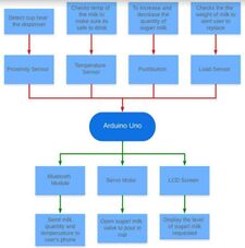
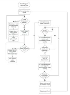
The Coffee Barista consisted of four sensors and three actuators. It made use of the DS18B20 temperature probe sensor, the HX711 weight sensor, the ultrasonic sensor, and two pushbuttons. The three actuators used were the LCD screen, two servo motors, and the HC-06 Bluetooth module. The general function of each of these sensors and actuators can be seen in Figure 1. These sensors and actuators followed the algorithm seen in Figure 2.
TinkerCad Prototype Simulations[edit | edit source]
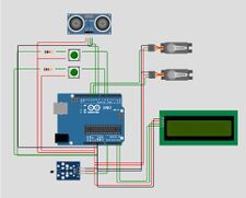
Based on the block diagram and algorithm, a TinkerCad simulation was created, as seen in Figure 3 and can be viewed by clicking here. Due to the limitations of the simulation program, only a portion of the sensors and actuators were able to be included in the circuit. The two pushbuttons, LCD screen, and the ultrasonic sensor were implemented almost identically to the physical circuit, with slight modifications to what is displayed on the LCD screen. The weight sensor, HC-06 Bluetooth module, and the DS18B20 temperature probe sensor were not available on the simulation program. The temperature probe was simulated with a similar temperature sensor in a separate simulation, however there was nothing similar to use as the weight sensor or the Bluetooth module. The main functions of the Coffee Barista were able to be replicated, with the simulated circuit only missing the weight sensor and the Bluetooth module, since the majority of the circuit operation is dependent on the on the user’s specified milk and sugar quantity.
Sensors and Actuators[edit | edit source]
Pushbuttons[edit | edit source]
The pushbuttons used in this project were for making personalized selections of milk and sugar quantities. This actuator was the easiest to implement within this circuit as there were no additional libraries required within the Arduino code. The circuit consisted of two pushbuttons and required a 10kΩ for each pushbutton. The red pushbutton was used to make the desired quantity selections which means the more times the user pressed the button, the more the quantity increased. The green pushbutton was used to select the quantity, so upon pressing it the appropriate servo would turn 90° for the appropriate amount of time.
Servo Motors[edit | edit source]
This project consisted of two mini servo motors. Each servo motor was responsible for dispensing milk or sugar into the coffee cup. The user inputted their milk/sugar preference using the pushbuttons, and the servo motors would turn 90° for the appropriate amount of time. The more quantities the user selected, the longer the servo motor would stay in the “open” position, before returning back to its original position. The servo motors have a GND wire, VCC wire, and a Signal pin which was connected to the pulse width modulation pin (PWM) on the Arduino. The servo motor required one additional library, the Servo.h library. The servo motors go through if-else-if statements to determine how long to hold the “open” position (hold the 90° position) according to the user’s preferred input.
Ultrasonic Sensor[edit | edit source]
The HC-SR04 ultrasonic sensor was used to detect if a coffee mug is placed under the dispensers. The ultrasonic sensor has a GND, VCC, TRIG, and ECHO pin, it also does not require any additional libraries to operate. The ultrasonic sensor measures distance by sending sound waves in the direction of a cup, while a timer is started. The cup then reflects the sound waves back to the ultrasonic sensor. The receiver picks up the reflected sound waves and stops the timer. The distance travelled is determined by dividing the time it takes for the wave to return by the speed of sound. The ultrasonic sensor is initialized using the pins from the Arduino board. The code within the void setup was declaring the TRIG pin as OUTPUT and the ECHO pin as INPUT and the main body code sends/receives the sound waves and calculates the distance between the cup. An if-else-if statement was included to check if a cup is placed under the dispensers. If the cup is not detected, then the user will not be allowed to input any quantity of milk or sugar.
LCD Screen and I2C Serial Adaptor[edit | edit source]
The LCD screen is used to prompt and display the quantity of milk and sugar the user selected. Originally, the LCD screen required 8-16 pins to display information. Fortunately, the I2C Serial Adaptor reduced the number of pins required to 4, including the GND, VCC, SCL and SDA pins. The SCL and SDA pins connect to pins A4 and A5, respectively. The LCD Screen and I2C Serial Adaptor (LCD-I2C) required one additional library, the LiquidCrystal_I2C.h library. While using the LCD-I2C, the code requires “lcd.xxx” to instruct the screen what to do. The LCD-I2C prints the “Milk Quantity” prompt in the first row and the user’s desired quantity is printed to the second row.
Temperature Probe Sensor[edit | edit source]
The DS18B20 temperature probe sensor was chosen to monitor the temperature of the milk since it is necessary to ensure it stays at a safe temperature. It was easy to implement and liquid proof, making it suitable for this application. This probe required two different libraries, the Wire.h library and the DallasTemperature.h library. The circuit for the probe was quite simple to build and only required one 4.6kΩ resistor. The GND wire of the temperature probe was connected to the GND of the Arduino, the VCC wire was connected to 5V from the Arduino, and the DQ wire was connected to pin A0 of the Arduino. The code sends the command to retrieve the temperature in Celsius. That value was then compared to the safe storage temperature of cows’ milk as stated by the USDA, 4°C. If the temperature that was read was greater than 4°C, a notification was sent to the phone via the Bluetooth module and the LCD screen, and the servo motors were not turned, ensuring that no users were at risk.
Weight Sensor[edit | edit source]
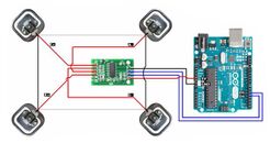
The weight sensor chosen for the project was the HX711 weight sensor. This was the most challenging sensor to integrate into the circuit design, as it required a lot of code and preliminary work. A preexisting project[3], which created a scale using the same sensors, was modified help in the creation of the weight sensor. It used the HX711_ADC.h library and required multiple integers throughout. The circuit construction itself was also particularly challenging, as it was necessary to connect the four weight pads and the amplifier in a specific manner, seen schematically in Figure 4. Each weight pad had 3 wires which had to be connected, and some of those connections had to be connected to the amplifier. This made creating this circuit very difficult, as it was challenging to ensure a good connection was made between wires. To add to the difficulty, the wires did not fit into the amplifier, so it was necessary to include additional circuitry to make this connection happen. Once the circuit was built, it had to be calibrated using the Calibration code from the HX711_ADC.h library. This code was very complex and hard to understand, however following the instructions was fairly straightforward. Running the code, placing a known weight on the scale and entering it into the serial monitor resulted in a specific calibration factor. This calibration factor was then declared in the actual project code, in order to obtain the most accurate reading possible. The code used for initializing the weight sensor was used to assign the pins used on the Arduino for the weight sensor and create the load cell. Additional code was used in the void setup to initialize the weight sensor. It declared the calibration factor calculated from the example code and tares the scale. This means that each time the code was reuploaded to the Arduino board, the scale was set to zero, even if there was weight on it. This had to be taken into account when setting the threshold weight in the body of the code, which is set to -1. As mentioned earlier, the scale executes the tare operation every time the code is uploaded, meaning that even though weight from the milk storage container is already on the scale, it is set to zero. The negative threshold accounts for the fact that as more milk is used from the storage container, the scale will read a more negative value. The values that are printed to the serial monitor helped during the debugging/demonstration process to understand what was happening in the code and when. These are not necessary in the code that would be provided with the product when supplied to the customer.
Bluetooth Module[edit | edit source]
The HC-06 Bluetooth module was used to send alerts to the user’s phone, based on the results of certain sensors. If the temperature of the milk reached too high or if the milk ran low in the storage container the alerts were sent. The HC-06 had multiple compatible libraries to choose from, however the Dabble library was chosen for the project. Since the Dabble library was used, the RX and TX pins of the Bluetooth module had to be connected to pins 3 and 2 of the Arduino respectively. This was because the functions within the Dabble library set these values, meaning they cannot be easily changed by the programmer. Using Dabble greatly simplified the code, as implementing the library was very easy. It also had an app to download on the phone, which helped alleviate issues which occurred when trying to connect the phone to the Bluetooth. The largest challenge arose simply from connection errors between the phone app and the Bluetooth module. Troubleshooting these connections issues were simplified with the Dabble app, as there was an icon to indicate when a successful connection was made. The first function Dabble.processInput(); must be called before including any additional commands for the Bluetooth module, to ensure a line of communication is made between the phone and the Bluetooth module. The following code, Terminal.print(); is what controlled what was sent to the phone. This same structure of code was used for both the temperature sensor and the weight sensor.
Schematics and PCB[edit | edit source]
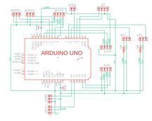
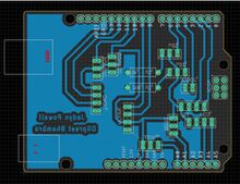
Based on the block diagram, Figure 1, and algorithm, Figure 2, a schematic was designed to create an Arduino shield, as seen in Figure 5. Using the schematic, the PCB was created to house the components used in the circuit. The PCB allowed for clean connections between each component and Arduino, as shown in Figure 6. Pin headers were used to allow for easy connect and disconnect of the circuit components. All ground pins of the Arduino were connected in order to maximize current flow. During the design process, it was ensured that no wires crossed, as this PCB was a single layer PCB. Multiple iterations of the design were necessary to eliminate crossed wires from the design. Placement of components was also taken into account during the design process as certain sensors/actuators, such as the Bluetooth module, were soldered directly onto the PCB board. Extra room had to be allocated to ensure a good fit on the board. The placement of the pins for the ultrasonic sensor was also intentional, as the proximity sensor had to be located under the LCD screen and pushbuttons. The pins allocated to the various sensors and actuators were specifically chosen to optimize wire placement on the PCB and minimize unwanted traces and unnecessary trace lengths.
Implementation[edit | edit source]
Prototype[edit | edit source]
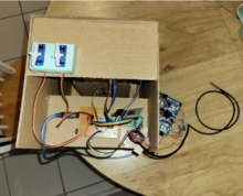
The full circuit was built and tested, and was fully functioning as seen here. Then, a full prototype for the circuit, as seen in Figure 7. This incorporated all components of the circuit, leaving the only thing unrealized was the storage method of the milk and sugar. This allowed for a more accurate representation of the actual product, making testing much easier. It also allowed for the opportunity to interact with the product in a way very similar to which the actual users would, giving a much better understanding of how the design met the customer constraints.
Sensors and Actuators[edit | edit source]
Pushbuttons and LCD Screen[edit | edit source]
The two pushbuttons and the LCD were the first sensors and actuators to be implemented. The majority of the circuit operation is dependent on the user’s specified milk and sugar quantity, so it was necessary to have these sensors and actuators functioning first. The two pushbuttons were chosen since they are a very simple, intuitive way for the user to input their selected quantity. One button was used to increase the amount selected, and the other button was used to confirm the amount and dispense it. The LCD screen was chosen as it was a very straightforward, direct way of communication information and instructions to the user. The LCD screen prompts the user to input their selected milk quantity, then their selected sugar quantity. It also serves as a convenient way for the user to see their selected quantity, so they are able to see their selected quantities in real time and make adjustments before dispensing the milk and sugar.
Servo Motors[edit | edit source]
The operation of the servo motors was directly dependent on that of the two pushbuttons, making implementing them afterwards a very logical choice. The servo motors were chosen as they are responsible for controlling the dispensing mechanism and it was very easy to open and close a storage container lid by simply adjusting the turning angles, and durations of the servo motors within the code. One servo motor was used to control the milk storage container, and the other servo is used to control the sugar storage container. Each servo operated separately, one at a time, so milk was dispensed first, followed by sugar. They were dispensed by setting the servo motor to the “open” position (turned 180° from its original position), then returning it to the closed position (the original position). The duration that each servo motor stays open is dependent on the selected quantities of milk and sugar, so the higher quantity a user selects, the longer the servo motor will remain in the “open” position. Arbitrarily pre-set times were assigned for each quantity which dictated how long the servo remained “open” before closing again.
Ultrasonic Sensor[edit | edit source]
The ultrasonic sensor was used to override control of the servo motors, pushbuttons, and LCD screen, making it necessary for the servo motors to be operational before the ultrasonic sensor was implemented. The ultrasonic sensor was used to ensure that the milk and sugar did not dispense if there was no coffee cup present. The use of the ultrasonic sensor was a very intuitive one, as setting a threshold distance and detecting whether something was present or not is a very common application of an ultrasonic sensor. If there was nothing detected within the specified threshold distance which was specified to be 5cm in the code, the servo motors were overwritten and were not permitted to turn to the “open” position. This ensured that no mess was made, and that nothing would dispense. Also, if there was no cup detected within 5cm of the sensor, no input was read by the pushbuttons and the LCD screen read “Place cup”. This was a clear, straightforward way to communicate instructions to the user and help ensure easy operation of the Coffee Barista.
Temperature Probe Sensor and Bluetooth Module[edit | edit source]
Since the Coffee Barista was used to store cows’ milk, it was necessary to ensure those storage standards met those declared by the USDA. Monitoring the temperature of the milk to ensure that it remained within the acceptable storage temperature was necessary. The DS18B20 temperature probe sensor was chosen to monitor the temperature of the milk as it was easy to work with and liquid proof, making it suitable for this application. It was also necessary to notify the user when the temperature of the milk rose above the safe storage level and using the Bluetooth module was a clear solution to this issue. Using the Bluetooth module ensured that the user received the alert on their phone, making it highly likely that they would see it and be able to alleviate that issue. The Bluetooth module was compatible with multiple libraries, however the Dabble library was chosen for use. This was because the Dabble library was very easy to implement and use, had a phone app that was easily compatible, and coding was very straightforward.
Weight Sensor[edit | edit source]
The final sensor integrated into the circuit was the HX711 weight sensor. This was because the weight sensor also required use of the Bluetooth module to send a notification to the user. The weight sensor was used to monitor the amount of milk in the storage container. It was chosen as it was easy to monitor the weight of the storage container, and if that weight dropped below a specified threshold, an alert was sent via the Bluetooth module. Again, using the Bluetooth module was a clear solution to this issue, as the user received the alert on their phone, making it very likely that they would see it and be able to alleviate that issue. The same Dabble library was used, for the same above stated reasons.
Results and Evaluations[edit | edit source]
Future Work[edit | edit source]
When the circuit detects that the temperature of the milk is above a safe storage level, an alert is sent to the phone via the Bluetooth terminal. An idea that was unable to be realized was including a Peltier to cool the milk. Once the temperature of the milk was detected to be too high, not only would an alert be sent to the phone, but the Peltier would also automatically turn on in order to cool the milk. Another unrealized idea was to have the coffee itself dispensed from the Coffee Barista. Rather than just dispensing milk and sugar into a cup of already made coffee, the machine itself would also brew and dispense coffee. Including a weight sensor for the sugar, the same way one is included for the milk, was also unrealized, simply because the second set of weight sensors would not arrive within the project constraint time.
The chosen HX711 weight sensor functioned for its purpose, however the readings were pretty inaccurate, even after using the correct calibration factor. A different, more accurate, weight sensor may be implemented in place of the HX711 in the future.
Finally, including some method of stirring the coffee was also unrealized. The original idea was to use a stir stick attached to a DC motor, however, upon further examination, it was determined that this method was unhygienic, as the stir stick would have to be removed and washed after each use and would be difficult to implement within the time constraints of this project.
Conclusion[edit | edit source]
The Coffee Barista was an automated milk and sugar dispenser, with quantities that were specified by the user using pushbuttons and included an LCD screen that displayed the specified quantities. It also monitored the temperature and quantity of the milk storage, to ensure that it stored safely and did not run out. After the end of the five-week timeline, the Coffee Barista was fully functional, and all four sensors and three actuators operated as expected. The project was a success, and both group members gained very valuable experience in the engineering design process, circuit design, and prototyping and debugging. Although the project was a success there are multiple areas for future improvement, including but not limited to, adding a cooling element, improving the accuracy of the weight sensor and adding a stirring mechanism.
See below for the full detailed report which further details code and testing/debugging, collaboratively written by Jadyn Powell and Dilpreet Bhambra completed for our ECE 2242 Principles of Design course.
References[edit | edit source]
- ↑ Home and Garden Information Centre, "SAFE HANDLING OF MILK & DAIRY PRODUCTS," Home and Garden Information Centre, 8 March 2007. [Online]. Available: https://hgic.clemson.edu/factsheet/safe-handling-of-milk-dairy-products/ . [Accessed 6 March 2022].
- ↑ United States Department of Agriculture , "How long can you keep dairy products like yogurt, milk, and cheese in the refrigerator?," United States Department of Agriculture , 17 July 2019. [Online]. Available: https://ask.usda.gov/s/article/How-long-can-you-keep-dairy-products-like-yogurt-milk-and-cheese-in-the-refrigerator#:~:text=Milk%20can%20be%20refrigerated%20seven,or%20go%20to%20FDA's%20website.. [Accessed 6 March 2022].
- ↑ Indrek, "Arduino Scale with HX711 and 50kg Bathroom Scale Load Cells | Step by Step Guide.," YouTube, 17 April 2020. [Online]. Available: https://www.youtube.com/watch?v=LIuf2egMioA . [Accessed 20 March 2022].