
This article provides a detailed how to for construction and use of this bailer as well has some design. A discussion on the application of this system and its bales is also included as well as a brief introduction to alternative machines.
Baling materials on such as hay, straw or leafs has many advantages as these bales are typically used to store excess materials or feed animals. Straw bales are also used as a building material for construction. This practise started in North America as early as the 1800's, and has recently seen a resurgence as part of the green and natural building movement. Straw bales are cheap and available construction material, since straw is a ubiquitous agricultural byproduct. These bales can provide both building insulation and structural support. The availability of this potential construction material deems its consideration as an appropriate technology. Large costs associated with mechanical combines and farmers with small plots of land necessitate a low cost alternative. There are many options available and this article examines A Hand Powered Hay and Leaf Baler made by Larry McWilliams that is on the CD3WD. The purpose of the CD3WD project is to help the 3rd World help itself, contents can be found here. This article provides a much more detailed how to for construction and use of this bailer as well has some design. A discussion on the application of this system and its bales is also included as well as a brief introduction to alternative machines.
Considerations[edit | edit source]
Access to Baling Materials[edit | edit source]
Materials to be baled exist in all parts of the world where this is agriculture. Cereal plants grow in all parts of the world, except very dry deserts and the ice-covered poles.[1] But more specifically, straw is a by product of cereal plants bales made of straw are used as a construction material. Straw is what remains after the grain and chaff have been removed; it is also known as the stalk of the plant. Africa is home to many native cereal plants, and colonization brought many other species to the area.[2] In other words this technology can be useful in almost any part of the world.
Access to Building Materials and Ability to Build[edit | edit source]
The baler that is detailed below was made using power tools and nominal wood. This is because these are the materials and tools that are available, and those which I have developed skills working with. These are not available around the world, but it is possible to make this structure out of different materials while using simpler tools. In the construction section there is a table for suggested and potential tools to build this baler. A skilled craftsman would be able to recreate this structure. In the case where a group was travelling to an area where these tools and materials were unavailable, a simple solution would be to pre cut and transport them leaving final assembly till the final site is reached. A full analysis of alternative balers should be conducted before this occurs.
Applicability of Bales[edit | edit source]
Straw bales can be used in construction and the typically application is for low cost, low environmental impact housing. Housing is a seemingly basic provision which provides families a place to stay warm, sleep, interact with each other as well as provide a place to shelter themselves from potential dangers in the environment including disease. Having a home has many benefits and owning one serves as a stepping stone to future success. Straw Bale buildings are cheap and effective use of renewable and local resources. Straw is also a by-product which is commonly burned,[3] using it as a building material sequesters carbon that could potentially end up in the atmosphere. Bales also have agricultural purposes, as this is a potential source of food or bedding for animals. Storing bales can be useful during winter months or periods of drought in agricultural applications. It is important to note that regardless of use, bales should be kept dry and free from insects as they will rot.
Engineering Principles[edit | edit source]
The use of a bale for structural applications is based on a few parameters.[4] Moisture content since bales need to be dry to prevent rotting while dry density determines the strength of bales. The equation for density, [kg/m3] is found here:

The density of a bale is based on the compressibility of the material and the stress exerted by the piston. Studies have shown that when laid flat, bales with a higher density fail at a higher ultimate load.[5] Further studies have shown a correlation between density and modulus of bales, but orientation has a larger effect on mechanical properties.[6] Straw bales are used to form a composite wall with plaster on either side of the bales. When these plastered walls are subjected to a concentric compressive load it acts like a composite column with the plaster taking the majority of the load. The straw primarily provides lateral bracing for the plaster skins, while taking a small part of the compressive load. If lateral bracing is insufficient, local buckling of the thin plaster layer will cause failure. Straw bales also provide insulation in these composite systems.[4]For making bales the important thing to note is that a large piston force will result in denser bales which provides more structural sound bales. Denser bales should have decreased insulation properties because of the close proximity of molecules but further testing is required in this area.
The other factors that effect utility are history, as bales should not have been near moisture or mold, fiber length, and material composition. Straw bales are more suitable for building because the carbohydrates have been removed. Hay, which contains carbohydrates will naturally rot as insects and animals feed on it.
For this structure, all loads are negligible relatively to the resistance provided by the cross sectional area of members. Utility governed design, rather than strength or serviceability.
Construction[edit | edit source]
A prototype of the Hand Powered Hay and Leaf Baler was made using the tools listed in the table below. Figure 1a, shows a picture of the prototype that was built besides the original drawing and recommended layout. Changes were made to the original design for simplification and additional changes are reflected in the design depicted in Figure 1b.
-
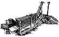
Fig 1: Original
-
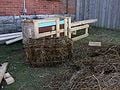
Fig 1a: Prototype
-
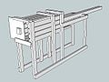
Fig 1b: Recommended


The table below shows the tools used to construct the prototype as well as basic tools that can be used to produce the same baler. Despite the fact that the prototype was built with power tools, basic tools in the hands of a skilled craftsmen will be sufficient to complete this task.
| Preferred Tools | Basic Tools |
|---|---|
| Circular Saw | Hammer |
| Drill | Hand Saw |
| Hammer | Measuring Tape |
| Measuring Tape | Working Bench/Clamp |
| Square | |
| Working Bench/Clamp |
Parts List[edit | edit source]
| Part | Name | Nominal Size | Prototype Length | Quantity | Recommended Length | Quantity |
|---|---|---|---|---|---|---|
| 1 | Bottom | 2X4 | 6' 10" | 2 | 6' 10" | 2 |
| 2 | Side Support | 2X4 | 2' 1 ¼" | 8 | 4' | 6 |
| 3 | Top Connector | 2X4 | 1' 6 ½" | 4 | 1' 6 ½" | 4 |
| 4.a | Chamber Side | 2X4 | 3' 4" | 4 | 3' 4" | 4 |
| 4.b | Chamber Side | 2X4 | 3' 10" | 4 | ||
| 5 | Chamber Top | 2X4 | 2' 4" | 4 | 2' 4" | 4 |
| 6 | Chamber Bottom | 2X4 | 4' 8" | 3[1] | 4' 8" | 3[1] |
| 7 | Bottom Connector | 2X4 | 1'3 ½" | 4 | 1'3 ½" | 3 |
| 8 | Rear Support | 2X4 | 39½" | 2 | 39½" | 2 |
| 9 | Restraint | 2X4 | 3' 9 ½" | 2 | 3' 9 ½" | 2 |
| 10 | Door Support | 2X4 | 1' 6 ½" | 1 | 1' 6 ½" | 1[2] |
| 11 | Piston | 2X4 | 8' | 2 | 8' **2 | 2 |
| P1 | Piston Back | Ply ½" | 12"x 14" | 1 | 12"x 14" | 1 |
| P2 | Piston Insert | Ply ½" | 12"x 12" | 1 | 12"x 12" | 1 |
| P3.a | Piston Block | 2x2 | 4" | 8 | 5" | 8 |
| P3.b | Piston Block | 2x2 | 3" | 8 | 3" | 8 |
| P4 | Piston Support | 2x6 | 14" | 2 | 14" | 2 |
| Door | Ply ½" | 18"x18" | 1 | 18"x18" | 1 |
[1] One piece must be riped into two, see procedure for details
[2] Optional, see procedure for details
Procedure[edit | edit source]
To make the building process quick, it is best to pre-cut many of the pieces. While this is advised make sure to build the piston once the chamber and other pieces have been assembled. This will make sure the piston actually fits in with what you've built. If there have been any alterations in the design or part assembly, they will become apparent when it is time for final assembly of the baler. Throughout the steps expand the images to see part names and spacing in more detail.
For all steps, using a square will make sure individual parts are made properly which makes assembly easier. Nails or screws can be used, but screws were used for personal preference and because they are more forgiving if mistakes are made or during the iterative prototyping process. Smaller pieces, like those found on the piston head, are also easier to attach with screws. Environmental factors come into play when determining the life of this structure. If it is to be used indefinitely, outdoor screws and a paint or stain will preserve the bailer and prevent weathering and other environmental wearing.
-
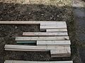
Fig 2: Pre-cut wood
-
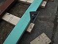
Fig 2a: Using a square & Marking Wood


This can be made by an intermediate craftsmen, a more skilled labourer will be able to make it faster and more accurately. Regardless of familiarity with tools, please follow appropriate safety procedures. If you are not as skilled, working with a partner or finding someone with more experience will make sure the baler is made accurately and safely.
Please read all steps before attempting construction.
Construct the chamber top. There is a 1/2" Spacing between the pieces because the twine will go through these gaps.


Construct the two chamber sides. Piece 2, the side support, is on the opposite side for the second chamber side. Otherwise the two pieces are identical. There is also a 1/2" gap in between pieces. In the recommended drawings, the side supports were increased to mid height on an average man. This allows the user to stand up during baling and tying, reducing the amount of stress on the user's back.


Construct the chamber bottom similar to the top. Connector locations are labelled in figure 7, and should line up with the side supports once assembled. The two skinner pieces on the sides can be made by ripping a 2x4 in half. The bottom piece of the prototype, shown in figure 8 does not include design changes to the structure.


Assembly the chamber by placing the top piece in between the two sides. Once this is completed the bottom can be dropped in by turning the structure upside down. A clamp will make sure the chamber is square. Figure 10 shows where the clamp was used during construction of the prototype.

.JPG)
After turning the baler upright, construct the back of the baler by attaching the rear support, restraint and top connector in that order. This way the new pieces will not fall over during construction. A helper is useful to hold pieces up, but if one is not available use a nail or screw to tack a piece close to where it needs to be and then secure the other end properly and then finally attach the original side.

There are two options to build the door. A door with a hinge can be installed but if hinges are not available try the option shown in the prototype. A section of the door support should be cut out to hold the door. If this second option is taken the top connector should be removed and a section cutout along the length of the door slot. Once cut these two pieces should be attached so they are flush against existing pieces allowing both the door to open and the bale to freely exit the chamber. The notches in these door support pieces should be cut with an appropriate tolerance so the door can slide a ¾' notch was used for a ½" door. These cuts should be made by a saw, a chisel can be used to remove the material in betwen cuts. Scrap wood can be used as a door handle.


If 2x2s are available the more complicated option for the piston head should be used. The piston blocks allow an insert (not shown) to be used during the bailing process. When the bale is ready to be tied, this insert can be removed and the blocks allow space for hands to reach into the baling chamber. Blocks can be adjusted for user hand size. A tolerance in the cut outs in P3.a should ensure the insert can be removed with ease. The end of P3.b should also match the start if the cut outs in P3.a. To make this cut jigs can be placed together in a jig similar to the one shown in Figure 15.
Blocks should be attached from behind, as you can see in figure 16. Two screws will resist the blocks from turning. Tacking one screw in and tightening the second will ensure the blocks remain where the marks are. Drilling pilot holes will ensure the plywood and blocks are not split in this step. Alternative the piston back can be used by itself, but it will be more difficult to keep the end of the bales compact.


Piston supports should be drilled prior to being attaching to the piston back. Like the blocks these should be attached from the back, after a pilot hole is drilled. Screws should be located in the large spaces in between blocks, to ease construction.

The two piston pieces should be cut and drilled according to the drawings. The cut out, located 47" from the front, allows the piston to lock into place while twine is tied. This makes sure the bale stays compressed in the chamber. The angle cut at the front allows a large range of motion during the baling process.

Attach both pistons to the piston head by placing a carriage bolt or axle in between the two pieces. Washers should be used at all interfaces (between wood and nuts). A scrap piece of wood should be put directly under the pistons once attached. This stops the piston head from falling over. Alternatively if bolts, nuts and washers are not available, the piston can be directly attached to the piston head. This removes the pivoting feature.


Cost[edit | edit source]
| Item | Quantity | Unit Price | Full Price |
|---|---|---|---|
| 2"x4"x8' | 20 | $1.77 | $35.40 |
| 2"x6"x8' | 1 | $4.29 | $4.29 |
| 2"x2"x8' | 1 | $2.26 | $2.26 |
| ½" Ply | 3 cutoffs | $3 | $9 |
| 4" 5/16" Bolt | 2 | $.69 | $1.38 |
| 5/16" Washer | 6 | $.11 | $.66 |
| 5/16" Nut | 2 | $.14 | $.28 |
| Total | CAD 53.27 | ||
Projected costs for constructing the recommended baler from entirely new wood came to around $55. Actual costs for the prototype that was built were much lower. This is because the prototype was built using recycled materials. If this were to be built on a farm it is likely that there is excess lumber which will reduce costs. In comparison farm jacks which is only one component in alternative technologies start around this price of $55. Like all construction projects an allowance should be included for potential cutting mistakes or losing materials, the lumber listed above has this included. Another way to drastically reduce costs is looking through cut off sections in stores (if they are available). Off cuts from other projects provide a cheap source of small materials and also divert materials from waste. Screws or nails are not included in this cost estimate as they are typically bought in bulk.
Baling[edit | edit source]
Procedure:
- Thread twine through gaps
- 2, 4 or 6 pieces can be used depending on material
- Thread twine only by door
- Cut enough twine to wrap around the entire bale, 6' is recommended but make sure there is enough initially because adding additional twine after is difficult
- Close door and begin baling by pushing piston
- Use small amounts to ensure good compaction
- Remove insert when enough material has been baled
- Thread twine around bale and tie
- Open door
- Remove bale by pushing piston
Please see the following video for the baling procedure:
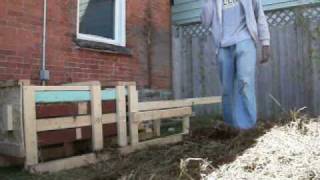
Please Note: This video shows the very first time I created a bale on the prototype. The entire process took under 20 minutes. With a helper and more practise this time will be greatly reduced so in a day enough bales could be made for a small home. The material being baled is also old and moist, both not useful properties. This was done simply because this material is what was available.
Machine Specific Recommendations[edit | edit source]
As the video showed it is possible for an individual to operate this baler, however it is more efficient to have two. One person can load the material to be baled while the second operates the piston. Switching reduces the monotony of the process while making sure neither worker gets tired.
Further improvements to the baler would include making it mobile by adding wheels. These wheels would have to flip up during the baling procedure to ensure the contraption does not move. This would allow the baler to be moved around a field to additional material that needs to be baled. Placing two wheels at the door end would allow this contraption to be pushed or pulled by human or preferably an animal. Since there is a large force being applied during the baling procedure, the entire structure is prone to moving in this direction. If this is a nuisance or hampers the bailing process dead weight can be added to the base of the structure which increases the frictional force resisting movement. Alternatively wedges or spikes that are attached to the structure would resist this motion as they act as anchors.
Bales expand once they have left the bailing chamber, if a specific bale size is required, experimentation or further work can be done to match chamber sizes with actual bale sizes. All bales made from non conventional methods, or mechanical balers, should undergo testing to assess their suitability for construction. Indicators of moisture content, dry density, wetting history, fibre length and material constitution are all necessary to determine usefulness as a building material.[4]Additional problems arise when using bales produced by machines like this for structural applications. The nature of the machine produces bales with some variability. Changes in bale density can be attributed to different piston packing force and the amount of material baled at a time. Hand tying in an enclosed area also introduces variability. Additional information on strawbale construction can be found here on appropedia, while the Wikibook on Straw bale construction is a slightly more comprehensive resource.
Alternative Technologies[edit | edit source]
There are alternative low cost baling contraptions. Box baling is a simple method, with a self-explanatory method. A simple backwoods hay baler can be found on the CD3WD. A research study conducted by the UK Department for International Development as part of the Livestock Production Programme provided evidence for the benefits of box bailing forage for milk producers in Tanzania. There are devices like Clark Dorman's Mobile pinestraw baler but this although significantly smaller and cheaper than combines it is still powered by a gasoline engine. The best alternative is used and developed by the Pakistan Straw Bale and Appropriate Building organization (PAKSBAB). PAKSBAB strives to apply appropriate building methods in this region of seismic activity to create earthquake resistant homes. For Straw Bale Fabrication a compression mould and human powered farm jack is used. This device is presumably more expensive than Larry McWilliams' design because it is steel, but it is simpler, faster, requires less human effort, and reduces variability in bales.
References[edit | edit source]
- ↑ BBC. Did you know? Cereals. http://www.bbc.co.uk/gardening/gardening_with_children/didyouknow_cereals.shtml (accessed April 13, 2010).
- ↑ Board on Science and Technology for International Development, Office of International Affairs, National Research Council. Lost Crops of Africa: Volume I: Grains. Washington, D.C.: National Academy Press, 1996.
- ↑ Government of Alberta. "Using Straw as a Farm Heating Fuel." Agriculture and Rural Development. January 6, 2010. http://web.archive.org/web/20170109090115/http://www1.agric.gov.ab.ca:80/$department/deptdocs.nsf/all/eng3127 (accessed April 13, 2010).
- ↑ 4.0 4.1 4.2 King, Bruce. Design of Straw Bale Buildings. San Rafael, CA: Green Building Press, 2006.
- ↑ Bou-Ali, G. Straw Bales and Straw Bale Wall Systems. M.Sc. Thesis,Tucson: University of Arizona, 1993
- ↑ Tattersall, Graeme H. EFFECTS OF DENSITY ON MECHANICAL PROPERTIES OF STRAW BALES. Thesis, Kingston: Queen's University, 2010.