
215 Solar for low power medical equipment

| Type | Photovoltaic system |
|---|---|
| Authors | Andrew Rodriguez Aiden Jackie Zeibert |
| Location | Humboldt, United States |
| Status | Deployed |
| Years | |
| Made | Yes |
| Replicated | No |
| Uses | photovoltaics, energy generation |
| Hardware license | CERN-OHL-S |
|---|---|
| Certifications | Start OSHWA certification |
Designed and constructed in Spring of 2022, the low-power/high-value PV system was built to provide power to low-end medical equipment such as glucometers and Continuous Positive Airway Pressure (CPAPs) in the event of a power outage or "brown out."
Background
[edit | edit source]Students of Cal Poly Humboldt's 2022 Spring semester Engineering 215 have partnered with Appropedia for a twelve-week design project. Appropedia is the world's largest organization dedicated to sharing appropriate technologies in a public setting. During the 12-week time, we will design a PV system to help with medical purposes when blackouts occur. A huge issue that has come to surface in recent volatile weather disasters is that people at home become susceptible to possible power outages rendering their at-home medical devices to fault. With our design, we would solve the problem of keeping the power on until emergency responders come.
Problem Statement
[edit | edit source]The objective of the design project is to create a portable photovoltaic charging station capable of providing power to essential low energy products such as phones, lights, glucometers, pulse oximeters, heart monitors, and low-end respirators.
Criteria:
| Criteria | Description | Rank (1-5)
(5 high) |
|---|---|---|
| High Replicability | Private individuals must be able to easily replicate the device. | 5 |
| High Portability | The device is able to be carried and moved by a majority of the population, including people with medical conditions that may compromise their lifting ability. | 4 |
| Low Cost | Price should remain affordable for a wide range of incomes. | 3 |
| Minimal Labor Requirements | Construction ought to remain simple with a low required labor threshold. | 2 |
| High Power Output | Device ought to be able to power basic medical equiptment. | 1 |
Prototyping
[edit | edit source]Our design process was heavily influenced by two prototypes. The first (Figure 1) served as a test of the feasibility of a 70lb solar system (the calculated weight if we had used a lead acid battery). Given that we were unable to transport the prototype up the stairs of an apartment complex without extensive effort we found that this design would not be suitable for a target market of individuals using at-home medical equipment. Our second prototype can be seen in Figure 2. Having decided what battery was not to be used we purchased the required materials based on what was found to be most affordable without inhibiting functionality. We found that our system (built outside of a box) was flawed on account of battery clamps being used in place of circular gauges. Prior to replacing our clamps our battery would regularly disconnect from the system during use, damaging our charge controller and rendering the device inert.
-
 Figure 1 - Weight Prototype
 -
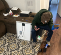 Figure 2 - System Prototype


Final Product
[edit | edit source]The final design is a lightweight portable generator capable of powering low power electronic equipment and medical devices. It features a 12V, 50W Monocrystalline solar panel with 165 cells. It is connected to a 12V, 30A Charge Controller. Also connected to this Charge Controller is a 12V, 24AH Lithium Iron Phosphate Battery. A 150W inverter is also connected to the Charge Controller. When constructing this project one will also need to add a 15A fuse on the positive terminal connected to the battery to protect other components from a power surge. Figure 3 shows the innerworkings of the device.
-
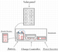 Figure 3 - Circuitry

Construction
[edit | edit source]Construction can be accomplished in under half an hour and entails little more than correctly connecting the positive and negative nodes of the system to their respective ends on the battery/charge controller. The steps for assembly are as follows:

The wires can be striped with the cutting section of a pair of plyers, by pressing until there is a slight pressure then twisting to remove the insulation section of the wire. There should be about half an inch of exposed copper wire. Two lengths of wire are needed for the solar panel and the battery requires one.

Connect the wires to the solar panel. The MC4 adapters are used for this solar panel. Unscrew the cap, insert the wire into the adapter, then tighten the cap to secure the wire. The adapters clip on to their corresponding MC4 components on the solar panel.

Cut the wire in the fuse opposite the fuse itself, then strip the ends of the wires as in step 1.

Insert one end of the wire for the battery into the end of the clamp with rubber insulation, making sure the copper wire is touching the metal of the clamp. Press down on the clamp with plyers to seal the wire in place. Repeat with the fuse and the other clamp.

The order of steps here becomes important. Attaching equipment in the incorrect order risks overloading the charge controller. Unscrew the screws on the top of the charge controller, then insert the wires into the middle two components on the charge controller. The fuse connects to the positive section and the wire connects to the negative section. Tighten the screws to secure the wires.

Unscrew the screws on the battery. Connect the negative side first and the positive side with the fuse second. Place the circle clamp over the hole and insert the screw, tightening to secure the connection.

Using the same methods as in step 5, connect the inverter to the charge controller on the right side.

The final step is to connect the wires from the solar panel to the charge controller. The solar panel connects on the left side.
Video Instructions
[edit | edit source]For greater clarification on the construction process refer to here. For clarification on maintenance more information can be found here.
Bill of Materials
[edit | edit source]The below materials do not include a pricing of the box that would hold the unit though any compartment roughly equitable to the size of a shoebox will suffice.
| Item | Amount | Cost per unit | Total |
|---|---|---|---|
| 12V 24Ah Lithium Iron-Phosphate Battery | 1 | USD 107.99 | USD 107.99 |
| 50W 12V Monocrystalline Solar Panel | 1 | USD 65.99 | USD 65.99 |
| 150W DC to AC Power Inverter | 1 | USD 17.99 | USD 17.99 |
| 30A Solar Charge Controller | 1 | USD 15.99 | USD 15.99 |
| Pack of Inline Fuse Holders & Fuse Blades | 1 | USD 7.99 | USD 7.99 |
| 10ft of Copper Wire | 1 | USD 15.90 | USD 15.90 |
| Battery Gauge Pack | 1 | USD 3.99 | USD 3.99 |
| MC4 Adapters | 1 | USD 4.99 | USD 4.99 |
| Grand total | USD 240.83EUR 207.11 <br />GBP 175.81 <br />CAD 298.63 <br />MXN 5,021.31 <br />INR 18,026.13 <br /> | ||
Operation
[edit | edit source]In order to operate the device plug a given device into the inverter's outlet. The light on the inverter will appear green if power is flowing and will not appear at all if the battery is dead.
Maintenance
[edit | edit source]Maintenance for this device entails replacing the solar panel and battery every 6-10 years.
Maintenance schedule
[edit | edit source]- Daily
- Disconnect object from Inverter that is being charged by outlet
- Place Solar panel and Tea-Box design inside of house when not in use
- Monthly
- Place solar panel outside in order to charge battery
- Clean solar panel with a microfiber or soft towel of any built up particles or dust
Every 7-10 Years (Beck 2019)/(Patel 2020)
- Examine Solar Charger Controller's LEDs when turned on. Make sure voltage is still reading at a normal level (not low)
- Replace Lithium Iron Phosphate Battery
After 20 years
- Check health of Solar Panel, replace if needed
Conclusion
[edit | edit source]Testing results
[edit | edit source]The battery can be fully charged in six hours with the solar panel. A high-end CPAP can run for three hours on the battery's power or six hours with the solar panel providing power. At maximum power draw, the battery lasts two hours, this is increased to three hours when connected to the solar panel. After some testing we also found that the battery has enough charge to fully power eight cell phones.
Discussion
[edit | edit source]When testing these devices we were able to determine and calculate what devices it could power and for how long. Our initial design was meant to power health equipment and with the acquired data, we calculated the power output of the health equipment and tested it letting us calculate the length of the time it could stay on.
Next Steps
[edit | edit source]This design was constructed specifically for a small output of amperage. In the future, this design is very versatile and the size is dependent on what you wanting to power. If needing a to power machines such as a CPAP's (Continuous Positive Airway Pressure) or Oxygen Concentrators, the future designer might need to look into a bigger battery, box and possible solar charge controller (Dependent on Voltage and Amperage input from the Medical Equipment). Portability was a huge factor into our design so we chose a small battery design for this reason, but having a medium sized battery could definitely be a possibility.
Troubleshooting
[edit | edit source]| Problem | Suggestion |
|---|---|
| Inverter Flashes Red Light | Ensure battery has not been disconnected during operation and damaged the charge controller.
If this has occurred, the inverter can be wired directly to the battery provided it is not lead acid. |
| Inverter shows no light | Make sure the battery is charged |
| Inverter is not charging product | Double check wiring and put solar panel outside for 5 minutes in direct sunlight to see if battery was not charged. |
Team
[edit | edit source]In the course of Spring 2022, Team Alpha Millennium consisted of
- Rodriguez, Andrew
- Vayo Tur, Aiden
- Zeibert, Jackie
References
[edit | edit source]- Beck, A. (2019). "Lithium Iron Phosphate vs. lithium-ion: Differences and advantages." Epec's Blog https://blog.epectec.com/lithium-iron-phosphate-vs-lithium-ion-differences-and-advantages (Feb. 24, 2022).
- Patel, J. (2020). "What are monocrystalline Solar Panels?" Price, size, weight, vs poly." Let's Save Electricity, Amazon.com, https://letsavelectricity.com/what-are-monocrystalline-solar-panels/ (Feb. 24, 2022).
| Authors | |
|---|---|
| License | CC-BY-SA-4.0 |
| Organizations | Cal Poly Humboldt |
| Cite as | Lonny, Jackie Zeibert, AV23, DrewRod (2022–2024). "215 Solar for low power medical equipment". Appropedia. Retrieved July 24, 2026. |