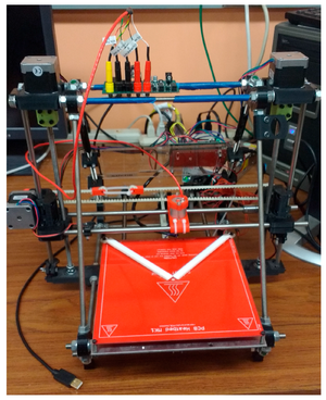
Scientists have begun using self-replicating rapid prototyper (RepRap) 3-D printers to manufacture open source digital designs of scientific equipment. This approach is refined here to develop a novel instrument capable of performing automated large-area four-point probe measurements. The designs for conversion of a RepRap 3-D printer to a 2-D open source four-point probe (OS4PP) measurement device are detailed for the mechanical and electrical systems. Free and open source software and firmware are developed to operate the tool. The OS4PP was validated against a wide range of discrete resistors and indium tin oxide (ITO) samples of different thicknesses both pre- and post-annealing. The OS4PP was then compared to two commercial proprietary systems. Results of resistors from 10 to 1 MΩ show errors of less than 1% for the OS4PP. The 3-D mapping of sheet resistance of ITO samples successfully demonstrated the automated capability to measure non-uniformities in large-area samples. The results indicate that all measured values are within the same order of magnitude when compared to two proprietary measurement systems. In conclusion, the OS4PP system, which costs less than 70% of manual proprietary systems, is comparable electrically while offering automated 100 micron positional accuracy for measuring sheet resistance over larger areas.
- please refer to the OSF for the BOM and designs (electrical and mechanical) as well as validation in the paper above
- Open Science Framework—Open Source 4 Point Probe. Available online:[1]
- Four Point Probe GUI and Software. Available online:[2]
- Literature review:[3]
Theory[edit | edit source]
The system used in-line four point probe method which works as depicted in the following figure:
Four needle with equal spacing is placed on the sample to be measured, and a current source is connected to the outer pair of needles. Then the voltage generated between the inner pair of needles is measured. Then the sheet resistance is measured with the formula:
Sheet Resistance = Constant * (Voltage measured / Current value)
Where the constant is 4.532 if the following conditions are true:
- The diameter of the sample is large compared to distance between the needles.
- The thickness of the sample is small compared to distance between the needles.
- The location of the needles is not too close to the edge of the sample.
If these conditions are not met, please follow the references in the paper to calculate the correction factor required.
Hardware[edit | edit source]
- Precision positioning system with four point probe on it. In this case a Prusa mendel is modified to hold a Jandel cylindrical four point probe.[4] A 3D printed probe holder available from[1]is used to fix the probe on the linear rod of the printer.
- Measurement circuit board and its printed case, available from.[1] Firmware for the Teensy on the circuit board is available from[2]
- 48 V power supply, used to power the current source of measurement circuit. Any current rating will do since the circuit will draw maximum ~10mA from the power supply.
- MicroUSB cable, for connecting the Teensy on the measurement circuit board to the computer.
- USB cable to connect precision positioning system to the computer.
- Power supply for the precision positioning system.
User Interface[edit | edit source]
The Java user interface can be downloaded from.[2] Go to Java folder there and download OS4PP.jar. Make sure Java Runtime Environment is installed, and double click the.jar file to run the software.
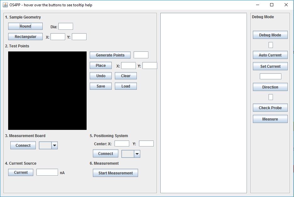
The user interface is designed so that the user just have to follow the numbered steps to fill the information needed to perform the automatic four point probe measurement. In the left part of the UI is where the user can enter information about the measurement. The middle part will report real time status of the ongoing measurement. The right part is reserved for debugging purposes where users can send command directly to the Teensy board in the measurement circuit board. Note that you can hover the mouse over each items in the user interface to display tooltip help.
The user interface will always save ongoing measurement data automatically to a results.csv file in the same folder with the software. Each time a new measurement is performed, the file results.csv will be overwritten. The file results.csv will contain the coordinate, current value and voltage measured at each point. The software also has the capability to save and load the configured measurement points to a config.csv file through save and load button. The file config.csv will be saved in the same folder with the software
Sample Geometry[edit | edit source]
Enter the diameter or X and Y dimensions of the sample in mm. Then click Round or Rectangular to enter the setting to the software.
Test Points[edit | edit source]
Enter the number of points to be automatically generated, then click Generate Points button. Alternatively, points can be added by manually entering the X and Y coordinate of the desired point and clicking Place button. Note that coordinate (0, 0) is the top left of the image box on the software. You can find out coordinate of desired point by hovering the mouse over the image box on the software.
Button Undo is used to delete the last point manually inserted, and button clear is used to clear all points. Save and Load button is used to save and load points coordinate data into a file named config.csv in the same folder with the software.
Measurement Board[edit | edit source]
Select the COM port that the measurement circuit is connected to in the drop down list, and click the connect button. Easiest way to know which COM port is to unplug the usb connection to the measurement circuit and take note which COM port is missing from the drop down list.
Current Source[edit | edit source]
Insert the desired current value in nanoampere unit from 10 - 10,000,000. Enter 0 to perform automatic current adjustment. Click Current button to enter the value to the software.
Positioning System[edit | edit source]
Insert the center coordinate of the positioning system bed (in terms of the printer coordinate system) in the X and Y text box in mm unit. Then select the COM port that is connected to the positioning system from the drop down list. Then click Connect button. Any system that accepts standard Gcode command over usb serial can be used as the positioning system.
Measurement[edit | edit source]
Click the Start Measurement button to perform automatic measurement. Place the sample on the bed and align the middle of the sample to the middle of the bed (the center coordinate inserted earlier in step 5). The positioning system will perform homing first and then will move the probe to each coordinate inserted in step 2. The measurement circuit will automatically perform measurement and display the results in the middle section of the user interface.
Error messages[edit | edit source]
- Sample not detected. Skip this point: It means either there is no sample connected to the probe or the resistance of the sample is too high such that it exceeds the current source compliance and renders it unable to source current.
- Too much difference between forward and reverse current, trying again: It means the voltage measured when the current direction forward and backward differs more than 10% thus the results might be invalid. Another measurement on the same point will be performed again to make sure.
- Input voltage range of ADC exceeded. Please reduce current: Voltage measured is larger than maximum voltage readable by ADC. This might be because the current value is too large
- Cannot check probe. Communication Error with Arduino: Wrong or no reply from Teensy board when sending check probe command.
- Cannot Set Current. Communication Error with Arduino: Wrong or no reply from Teensy board when sending set current command.
- Cannot perform measurement. Communication Error with Arduino: Wrong or no reply from Teensy board when performing measurement.
- Cannot enable current. Communication Error with Arduino: Wrong or no reply from Teensy board when enabling current.
- Cannot disable current. Communication Error with Arduino: Wrong or no reply from Teensy board when disabling current.
- Cannot switch forward. Communication Error with Arduino: Wrong or no reply from Teensy board when switching current direction.
- Cannot switch reverse. Communication Error with Arduino: Wrong or no reply from Teensy board when switching current direction.
Operations Flowchart[edit | edit source]
Limitations[edit | edit source]
- The current source can only source current from 10 nA to 10 mA. The measurement in nA range is not accurate, so it is recommended to set the current as high as possible while still not exceeding the maximum input voltage of ADC
- Even though the sample might be conductive, the contact resistance might be very high and makes it unable to perform measurement accurately or not at all. The probe tips used is optimized for ITO samples, and different probe might be needed for different sample. See[5] and[6]
See also[edit | edit source]
- Open Source Lab
- Building research equipment with free, open-source hardware
- Open source science
- Open-source hardware
- Open-source syringe pump
References[edit | edit source]
- ↑ 1.0 1.1 1.2 https://osf.io/kcbmq/
- ↑ 2.0 2.1 2.2 https://github.com/mtu-most/fourpointprobe
- ↑ Open source 4-point probe literature review
- ↑ http://www.jandel.co.uk/downloads/Jandel_four_point_probe_cylindrical.pdf
- ↑ http://four-point-probes.com/determining-the-best-choice-of-probe-tip-specifications-for-a-given-material/
- ↑ http://four-point-probes.com/four-point-probe-tip-specifications-applications-chart/


