Open-source RepRap 3-D printers have made distributed manufacturing and prototyping an affordable reality. This paper presents novel modifications to a RepRap design that increase RepRap capabilities well beyond just fused filament fabrication.
The design is a significantly modified derivative of the Rostock delta-style RepRap 3-D printer. Modifications were made that permit easy and rapid repurposing of the platform for milling, paste extrusion and several other applications. All of the designs are open-source and freely available.
In addition to producing fused filament parts, the platform successfully produced milled printed circuit boards, milled plastic objects, objects made with paste extrudates such as silicone, food stuffs and ceramics, pen plotted works and cut vinyl products. The multi-purpose tool saved 90-97% of the capital costs of functionally equivalent dedicated tools.
While the platform was used primarily for production of hobby and consumer goods, research implications are significant since the tool is so versatile and the fact that the designs are open-source and eminently available for modification for more purpose-specific applications.
The platform vastly broadens capabilities of a RepRap machine at an extraordinarily low price, expanding the potential for distributed manufacturing and prototyping of items that heretofore required large financial investments.
The unique combination of relatively simple modifications to an existing platform have produced a machine having capabilities far exceeding that of any single commercial product. The platform provides users the ability to work with a wide variety of materials and fabrication methods at a price of less than $1,000 providing users are willing to build the machine themselves.
The tool end effector (tool effector) permits easy and fast change out of mobile tools. It is necessary to use the other mobile tools covered in this section.
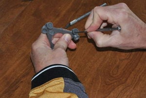
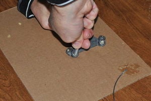
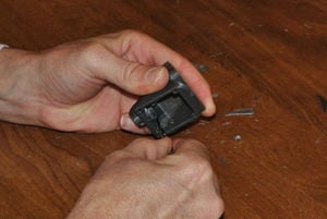
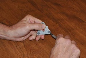
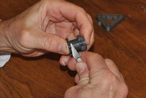
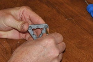
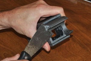
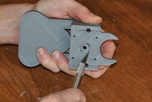
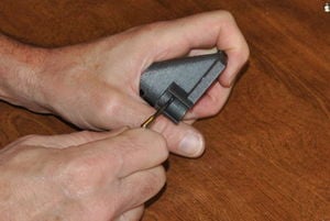
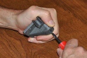
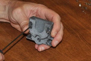
Dress the tool effector.With a precision knife and flat bladed screwdriver, clean the 12 magnet pockets in the printed tool end effector.
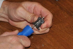
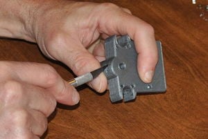
Test fit magnets.Starting with the magnets that engage with the connecting rod bearings, insure they all fit snuggly in their pockets. Magnets should fit tightly to maintain geometry - be careful not to over-dress the pockets so that the magnets become loose in them. 'Do not let the magnets slam together - they are brittle and easily break.
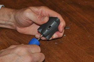
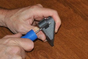
Remove magnets with a small screwdriver.Remove magnets from pockets using a small flat blade screwdriver to pry them out.
Epoxy magnets in their pockets.Mix a small amount of plastic epoxy per the instructions on the epoxy's packaging. Apply epoxy to the walls and floor of the magnet pockets that were cleaned and checked, above.
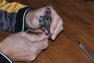
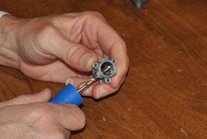
Press magnets into pockets with countersink facing out.Press magnets with countersink facing out into the pockets with epoxy. Magnets should be inserted so that nearest neighbors attract each other through the bottom of the pocket. This helps to keep them in place if the magnets are slightly loose in their pockets.
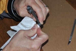
Remove excess epoxy.Remove excess epoxy from the interior of the magnets with a paper towel. HINT: Let the epoxy cure for a short time and use a small flat bladed screwdriver to scrape the gelled epoxy out, then follow up with a paper towel.
Set the end effector aside until the epoxy cures.
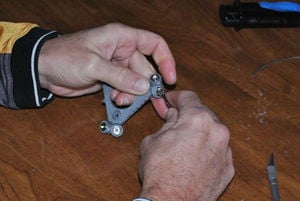
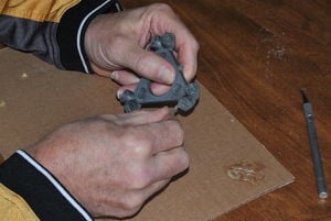
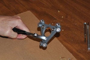
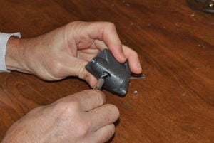
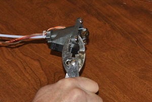
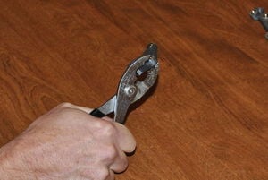
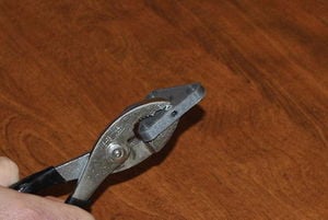
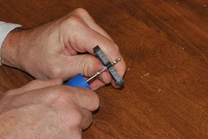
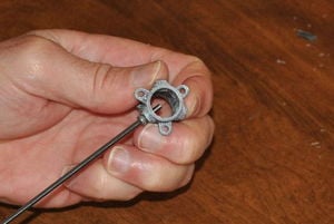
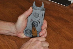
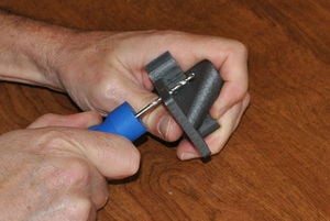
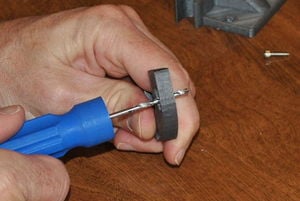
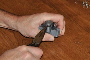
Epoxy magnets in tool mount pockets. Use pliers as shown, if necessary.Repeat the process with the magnet pockets for the tool mount, again orient the magnets on the top and bottom of the end effector so that they hold themselves in place. Use pliers to press fully into the pockets, if necessary.
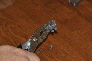
Use the precision knife and a flat bladed screwdriver to remove any remaining epoxy from the magnets' interiors. The surface that mates with the ball bearing must be free of all epoxy.
The print tool holds a hot end and is required for 3-D printing polymer filaments.
Remove floor material.Remove floor material that supported the overhanging parts of the print with a precision knife and flat bladed screwdriver.
Scrape hot end slot. Scrape clean the slot that the hot end will engage. Use the screwdriver as a scraper to remove protrusions from the interior of the slot and to remove loose material hanging into the slot.
Ream Bowden sheath passage.Ream the Bowden sheath passage with a 3mm drill bit, using the bit like a file.
Clean wire passage.Clean the wire passage with a precision knife.
Carefully dress bearing pockets.With the precision knife, carefully dress the edges of the bearing pockets. Do not remove too much material as the bearings are a press fit and must be held snugly in place.
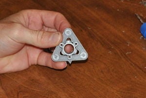
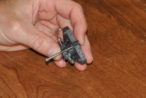
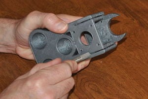
Fully prepped print tool.The fully prepped print tool should appear as pictured.
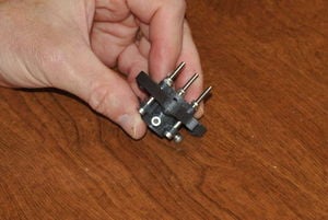
Nearly completed print tool.Follow the instructions for Assembling the Athena print effector. Print tool with hot end inserted should appear as pictured.
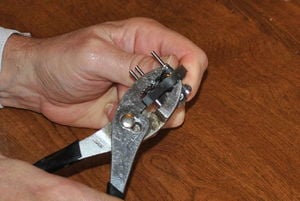
Press 3/8" ball bearings into pockets.Press the 3/8" ball bearings into their pockets with pliers. There is a small lip in the interior of the pockets that hold the bearings in place, the bearings should be pushed in past that lip and fit snuggly in their pockets. Warming the plastic slightly can facilitate insertion of bearings.
The circular tool holder is intended to hold tools that have a circular cross section, like a stirring stick/rod.
Carefully dress bearing pockets.With the precision knife, carefully dress the edges of the bearing pockets. Do not remove too much material as the bearings are a press fit and must be held snugly in place.
Press 3/8" ball bearings into pockets.With pliers or a vise, press the 3/8" ball bearings into their pockets. There is a small lip in the interior of the pockets that hold the bearings in place, the bearings shuld be pushed in past that lip and fit snuggly in their pockets. Warming the plastic slightly can facilitate insertion of bearings.
Press in retainer nut if required.If required to hold the tool in place, press an M3 nut in the slot printed in the tool holder. Use an appropriate M3 screw to press against the tool and hold it in place.
The spring mount tool holder is intended to hold tools that have a circular cross section and require some give as they are pressed into a workpiece, such as a felt tip pen or tangent knife.
Remove support material.Remove support material from the tool mount with pliers, carefully crushing and breaking away the support.
Remove any remaining support material with a knife.The support material must be completely removed to provide room for the screws and springs; remove any remaining with a precision knife.
Ream shaft openings.Ream the openings for the M3 x 35mm screws with a 3mm drill bit.
Ream tool retainer openings.Ream the openings for the tool retainer screws with a 3mm drill bit.
Ream bushings in base.Ream the bushings in the base of the holder with a 3mm drill bit. DO NOT over-dress these holes; the M3 x 35mm screws should just fit inside the holes. If the diameter is made too large, the sprung tool will suffer from too much back lash.
Carefully dress bearing pockets.With the precision knife, carefully dress the edges of the bearing pockets. Do not remove too much material as the bearings are a press fit and must be held snugly in place.
Suck nuts into their pockets with a M3 x 10mm screw.Fully seat the tool retainer nuts in their pockets by starting M3 x 10mm screws into the the tool holder and nut. Pull the nut fully into the pocket by tightening the screw. Loosen the screws when done seating the nuts.
Check clearance.Check the clearance between the tool mount and the tool base. The mount must be able to move freely in the space provided. Remove obstructions with the precision knife.
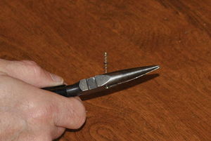
Cut springs from ball point pen.Cut springs from a ball point pen to about 6mm in length. Three 6mm long springs will be required.
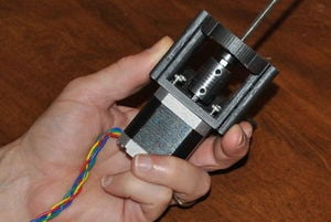
Assemble screws, springs and mount.The challenging part - Insert the tool holder in the base and rotate it so that the holes in the base line up with the holes in the holder. Press one of the springs into the space between the base and shaft mounts on the holder. Start an M3 x 35mm screw through the shaft mount in the tool holder, through the spring and through the base. Repeat with other two mount points. Refer to picture for proper orientation.
Secure holder with nylock nuts.Secure the tool holder with M3 nylock nuts. Tighten the nuts until just touching the tool holder - do not over-tighten.
Press 3/8" ball bearings into pockets.With pliers or a vise, press the 3/8" ball bearings into their pockets. There is a small lip in the interior of the pockets that hold the bearings in place, the bearings should be pushed in past that lip and fit snuggly in their pockets. Warming the plastic slightly can facilitate insertion of bearings.
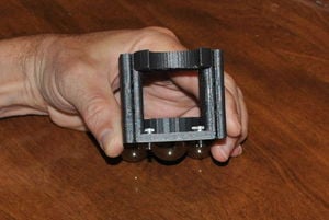
Exercise the tool holder and apply grease to the shafts as needed. The holder should move freely in the base and the springs should lift it completely from the base when the holder is at rest.
Fixed tools are secured in place by a structure made of 25mm x 75mm (1" x 3") rectangular extruded aluminum that replaces one of the vertical boards on the robot. The vertical aluminum member is 81cm long, the horizontal member is 15cm long. The horizontal member is held in place by a pair of 3mm (1/8") thick aluminum gussets secured with M4 x 12mm screws into tapped holes in the vertical and horizontal struts. The vertical member is secured to the robot's frame with M3 x 45mm screws that pass through the existing vertical board mount points in the idler and motor ends. 3mm holes are drilled and tapped (M3 x 0.5mm) for the extruder drive, placing it in the same position and orientation as shown in the MOST Delta frame assembly instructions. Larger holes are also drilled in the vertical member to permit the passage and concealment of wires.
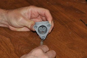
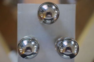
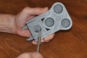
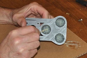
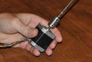
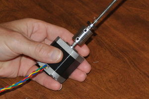
Tools are secured to the mount by a magnetic mount consisting of three rare earth magnets (19mm diameter x 12mm high (3/4" x 1/2") countersunk N52 magnets) mounted to the top of the horizontal member and three mating 25mm (1") diameter ball bearings on the tool holder. The magnets are held in place with stainless steel, countersunk M4 screws in holes drilled and tapped in the horizontal member. The position and orientation of the holes is set by use of a printed template (TBD).
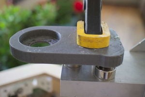
In order to assure that the tools are tightly secured to the mount, and in the case of the mill spindle, do not vibrate, the ball bearing pockets are over-sized. Ball bearings are epoxied into the tool holder while they are seated in the magnets on the horizontal mount.
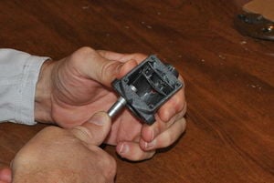
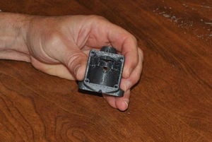
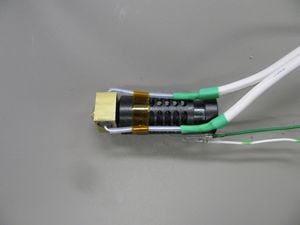
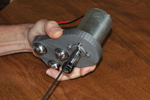
The mill spindle holder (spindle holder) accepts a low cost, 200-400W DC spindle motor that turns at 12,000 rpm when supplied with 48V power. The spindle comes with an ER11 collet that accepts 3.125mm (1/8") shank bits and end mills. These instructions assume the spindle has been properly wired to a suitable power supply.
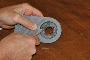
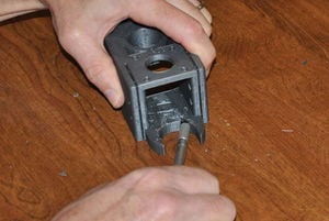
Remove floor material.Remove floor material from the spindle pocket with a precision knife and small, flat blade screwdriver. The base of the pocket should be made as flat as possible.
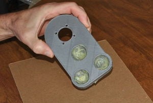
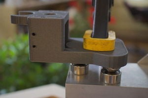
Engage ball bearings in their magnets.Place a ball bearing on each of the three magnets on the tool mount.
Mix epoxy and apply to interior of bearing pockets.Mix enough plastic epoxy to coat the interior of all three ball bearing pockets in the tool holder. Follow the directions on the epoxy's packaging paying attention to the ratio of resin and hardener. Apply a generous coating of epoxy to the interiors of the three ball bearing pockets.
Clamp the holder onto the ball bearings.Place the spindle holder so that the ball bearings are in their pockets. Clamp the holder to the tool mount and leave in place until the epoxy has cured for the amount of time specified in the epoxy's directions.
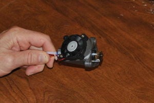
After epoxy cures, mount spindle.Mount the spindle to the holder with for M4 x 12mm screws and washers.
Completed spindle holder.
What can it do? See results (right) against a professional milled board (left)
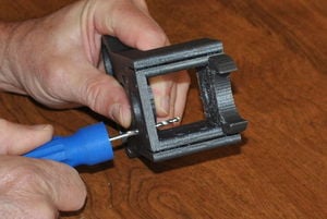
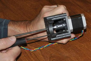
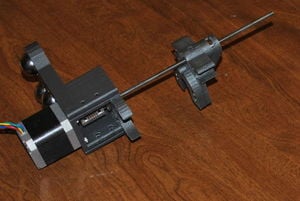
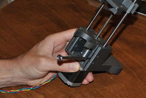
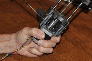
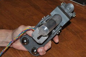
The syringe pump is useful if viscous liquids or pastes are to be printed. The coupling is boxed so as to constrain it, otherwise it acts as a spring.
Remove support material.Remove support material from under the syringe support with a suitable tool (pliers, putty knife, knife).
Remove support material from bearing pockets.Remove support material from the bearing pockets with a precision knife and small flat blade screwdriver.
Remove support material and floor from motor collar opening.Remove support material from the motor collar opening with a precision knife.
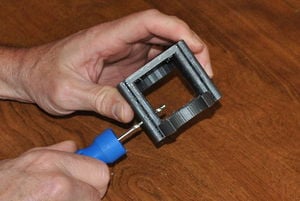
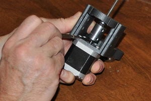
Clean the under side of the coupling box.Remove loose material from the under side of the coupling box.
Clean bearing pockets.Clean the bearing pockets in the outboard side of the coupling box. There are pockets in the interior and exterior of the box.
Ream motor mount screw holes.Ream the motor mount with a 3mm drill bit.
Ream clamp screw holes.Ream the clamp screw holes with a 3mm drill bit.
Remove obstructions from clamp slot.Remove obstructions from the clamp slot with a precision knife.
Engage ball bearings in their magnets.Place the 1" ball bearings in the magnets on the fixed tool mount.
Apply epoxy to bearing pockets.Mix sufficient plastic epoxy to coat the interiors of the three bearing pockets. Follow mixing instructions on the epoxy's packaging paying attention to proper proportions. Apply the mixed epoxy to the interior surfaces of the bearing pockets.
Clamp syringe holder to mount.Place the syringe holder on the bearings so that the bearings align with the pockets. Clamp in place and leave until epoxy cures.
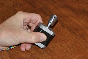
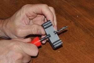
Coupling on the motor shaft.Place the 5mm x 5mm coupling on the motor shaft with one of the set screws facing the flat on the shaft. Do not tighten the set screws.
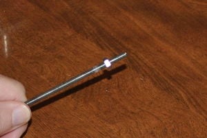
Start a nut on the lead screw.Start an M5 nut on the M5 lead screw and thread it up about 15mm.
Lead screw in coupling.Place the end of the lead screw with the nut on it into the coupling. Insert the lead screw so that it is about half way into it. Tighten the set screws to secure the lead screw to the coupling. Advance the M5 nut so it is against the coupling.
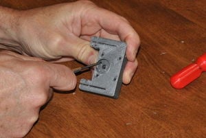
625zz bearing on lead screw.Place a 625zz roller ball bearing on the lead screw.
Load motor mounting screws.Load four M3 x 10mm screws and washers into the motor mount screw holes.
Attach to holder.Slide the lead screw and coupling into the printed syringe holder so that the motor mounting face is flush against the holder and the screw holes line up.
Secure motor.Secure the motor by tightening the four M3 x 10mm screws.
Compress coupling.Place a flat blade screwdriver between the coupling and motor and gently pry the coupling towards outboard side of the coupling box until the 625zz bearing is pressed firmly into its pocket, then tighten the coupling set screws against the motor shaft.
Clean carriage bearing pockets.Remove protrusions from the carriage bearing pockets with a small flat blade screwdriver.
Ream carriage securing screw holes.Ream the carriage securing screw holes with a 3mm drill bit.
Ream carriage lead screw passage.Ream the carriage lead screw passage with a 5mm drill bit.
Clean carriage captive nut and bearing pockets.Clean the captive nut and bearing pocket openings with a precision knife.
Ream plunger retainer mounting holes.Ream the plunger retainer mounting holes with a 3mm drill bit.
Ream plunger retainer.Ream the plunger retainer with a 3mm drill bit.
Mount plunger retainer.Mount the plunger retainer to the carriage with two M3 x 12mm screws and M3 nuts. Note the nut pockets in the back of the carriage. Do not tighten the screws.
Insert captive nut and bearing.Insert an M5 nut and the 625zz bearing into their pockets in the carriage. Make sure both are fully seated in their pockets. Use a screwdriver or similar tool to push them firmly in while supporting the carriage on a sturdy work surface.
Spin carriage onto lead screw.Spin the carriage onto the lead screw with the plunger retainer facing the motor end.
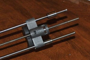
Press in guides.Press the 6mm drill steel guide rods into the clamps in the motor end. Use a flat blade screwdriver to gently pry apart the clamps.
Secure guides.Secure the guides with four M3 x 16mm screws, washers and nuts. Note nut pockets on interior of motor end clamps.
Slide on lubricated bearings.Slide one lubricated LM6UU linear bearing onto each of the guide rods.
Secure bearings.Align the carriage with the LM6UU bearings and secure the bearings to the carriage with M3 x 25mm screws with washers at both ends. Tighten the M3 nuts so that the bearings are clamped into the carriage.
Ream idler end clamp screw holes.Ream the idler end clamp screw holes with a 3mm drill bit.
Ream idler end lead screw passage.Ream the idler end lead screw passage with a 5mm drill bit.
Clean idler end bearing pockets.Clean the idler end bearing pockets with a precision knife and flat blade screwdriver.
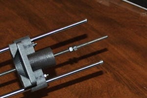
M5 nut on lead screw.Thread a pair of M5 nuts on the lead screw behind the carriage. Advance the nut about 2cm onto the screw.
625zz idler bearing.Place a 625zz roller ball bearing onto the lead screw.
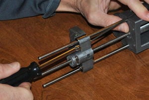
Press on idler end.Press the idler end clamp onto the guide rods. Secure in place with four M3 x 16mm screws with washers and nuts. Note nut pockets in the interior of the idler end clamps.
Press bearing into pocket and jam nuts.Advance the two M5 nuts so that the 625zz bearing is seated in its pocket in the idler end. Jam the nuts by tightening them together.
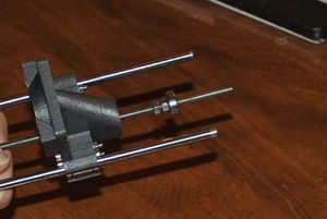
Bearing and M5 on outboard side of lead screwPlace a 625zz bearing on the lead screw followed by an M5 nut (an M5 nylock nut would be better).
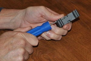
Secure syringe.Insert syringe plunger into the plunger retainer on the carriage. Place the syringe stops against the back of the syringe support. Push the plunger retainer up until the plunger is parallel with the syringe and tighten the plunger retainer screws.
Secure plunger. Secure the plunger to the carriage with the plunger wedge.
Secure syringe. Secure the syringe to the holder with the box clamp.