(Created page with "{|style="border:1px solid #000000; background-color: #ffff99; margin-left:.1em; margin-top:1px; -moz-border-radius:15px;" align="right" width="400px" !<center><big>Non-Inverti...") |
mNo edit summary |
||
| Line 1: | Line 1: | ||
{|style="border:1px solid #000000; background-color: #ffff99; margin-left:.1em; margin-top:1px; -moz-border-radius:15px;" align="right" width="400px" | {|style="border:1px solid #000000; background-color: #ffff99; margin-left:.1em; margin-top:1px; -moz-border-radius:15px;" align="right" width="400px" | ||
!<center><big> | !<center><big>RF Transmitter</big></center> | ||
|- | |- | ||
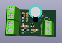
|<center>[[Image:RF_Transmitter.png|200px]]</center> | |<center>[[Image:RF_Transmitter.png|200px]]</center> | ||
Revision as of 01:20, 2 January 2018
 |
| OCI Page: RF Transmitter |
| Input: 9V, single ended signal |
| Output: Antenna Output |
This is a design from the Open Circuit Institute. More can be found HERE.
Description
A simple Radio Frequency Transmitter. The circuit includes a DC rejection capacitor, input low pas filter, and a resonant circuit for AM modulation. A tunable capacitor is used in order to generate a resonating carrier.
The design could be built on significantly - perhaps by adding an antenna trace rather than outgoing terminals. Add buffering circuits. Perhaps add input and output amplifiers. Add a simple mixer for an external modulator. The possibilities for extension are endless.
This design is made with reference to a design in Practical Electronics for Inventors, Third Edition
Design Files & Videos
Available at the Open Circuit Institute: http://opencircuitinstitute.org/content/rf-transmitter