This special page shows all uploaded files.
| Date | Name | Thumbnail | Size | Description | Versions |
|---|---|---|---|---|---|
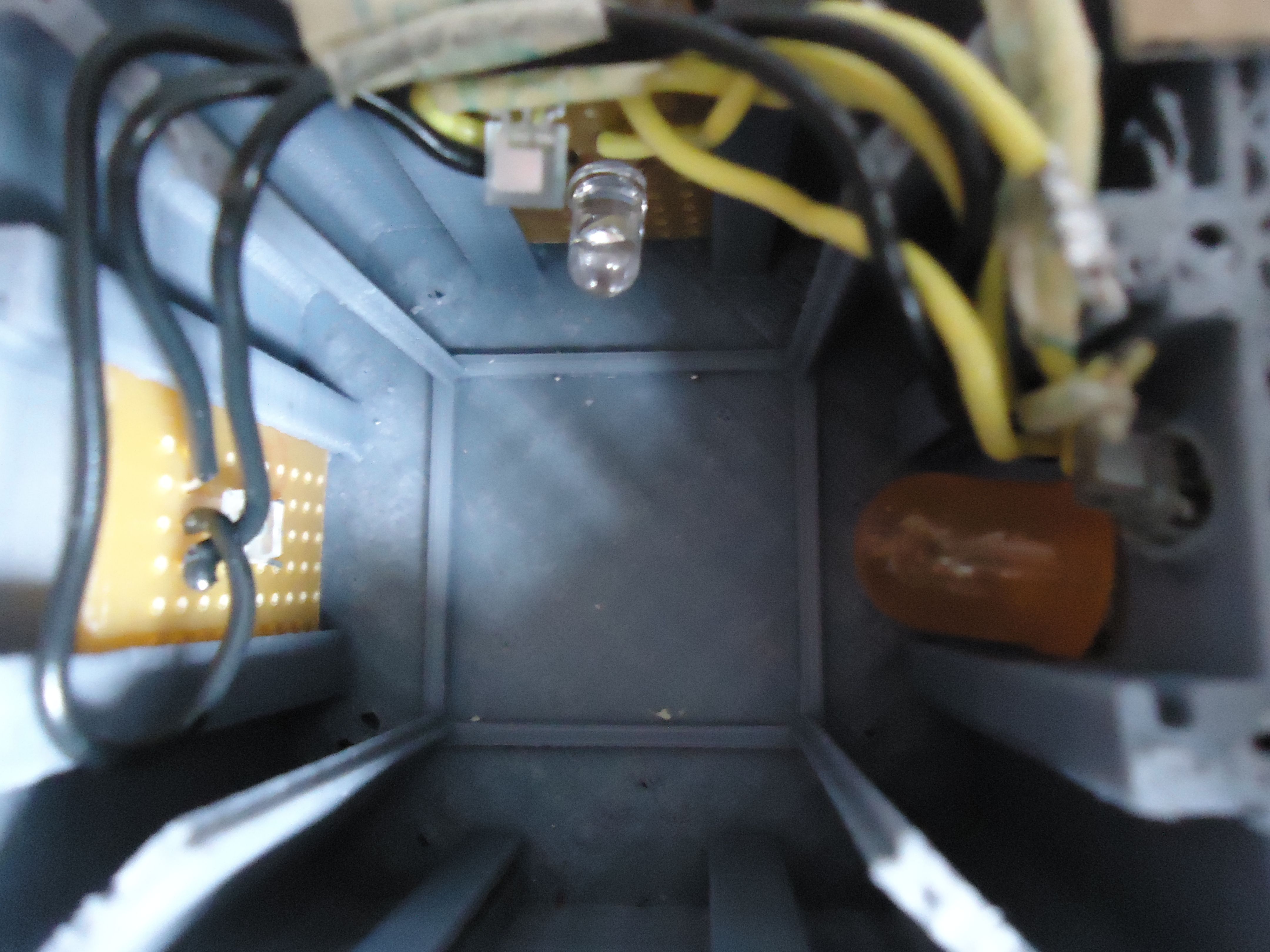
| 09:14, 18 May 2015 | Final Layout.JPG (file) |  |
1.22 MB | All PCBs in place, looking down the test tube case. From left to right: PCB3, PCB2, PCB1. The other part of the box is to the right, holding the Arduino and LCD. I took this photo. | 1 |
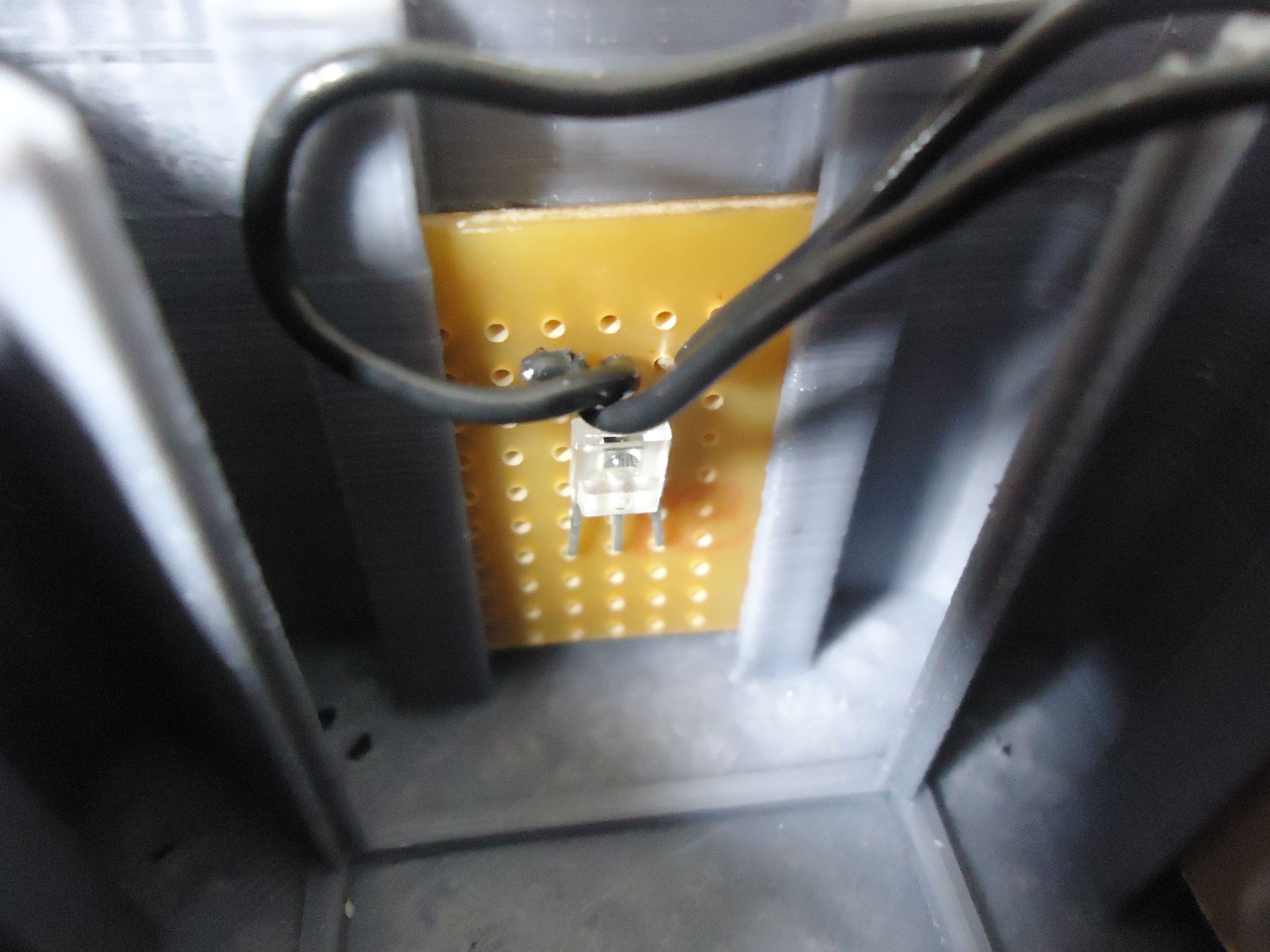
| 09:12, 18 May 2015 | Encode sensor.JPG (file) |  |
1.18 MB | PCB3. The third light to frequency encoder sensor pointing towards the test tube vault where the two LEDs are also pointed at. I took this photo | 1 |
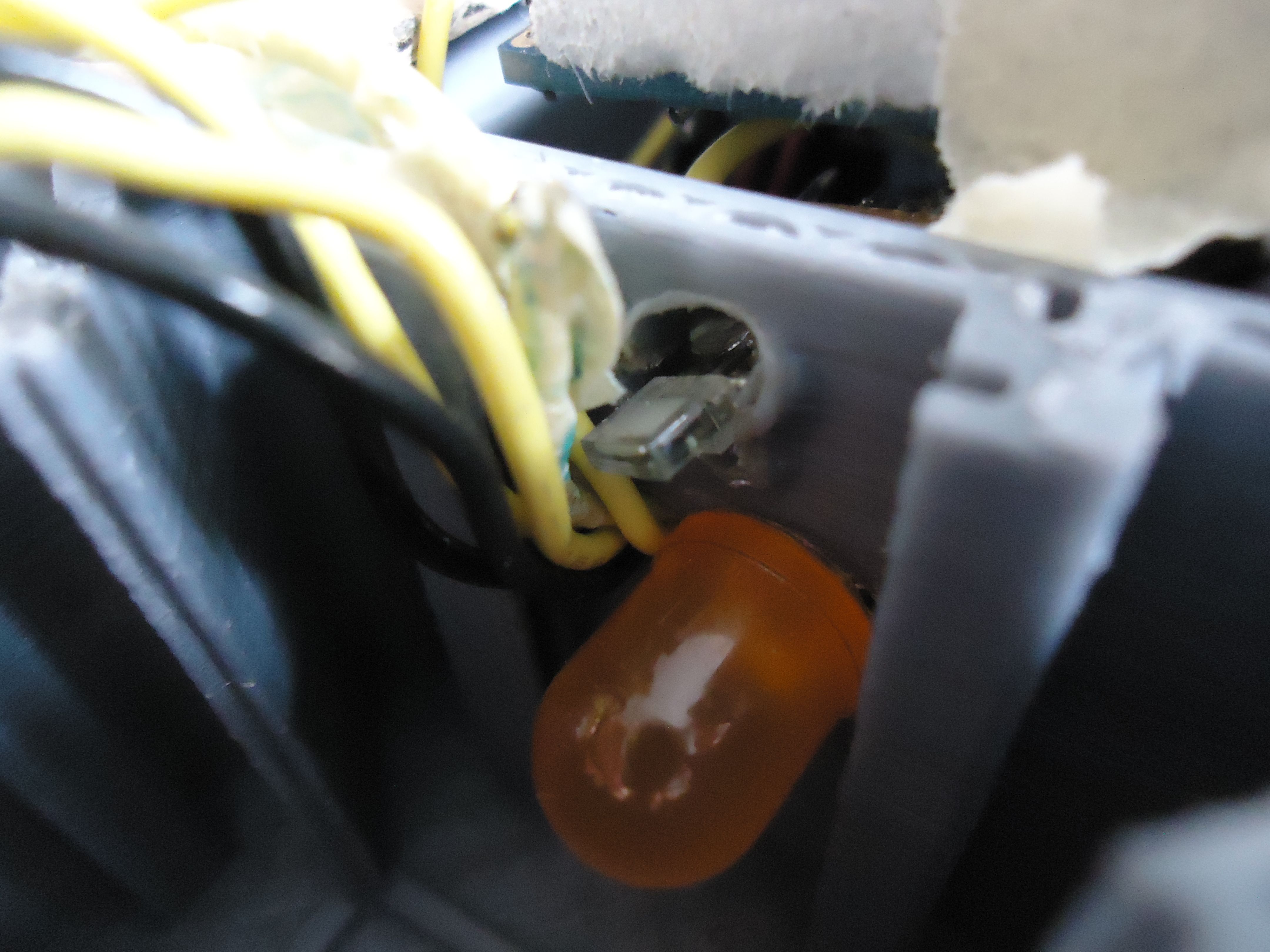
| 09:09, 18 May 2015 | Sensor LED2.JPG (file) |  |
1.09 MB | PCB1. Top: sensor pointing towards LED. Bottom: orange LED. Note the mistake: the LED was too big, so we had to put the PCB on the other side of the wall instead of the slide. The slide where the PCB should have gone is visible on the top right (out of... | 1 |
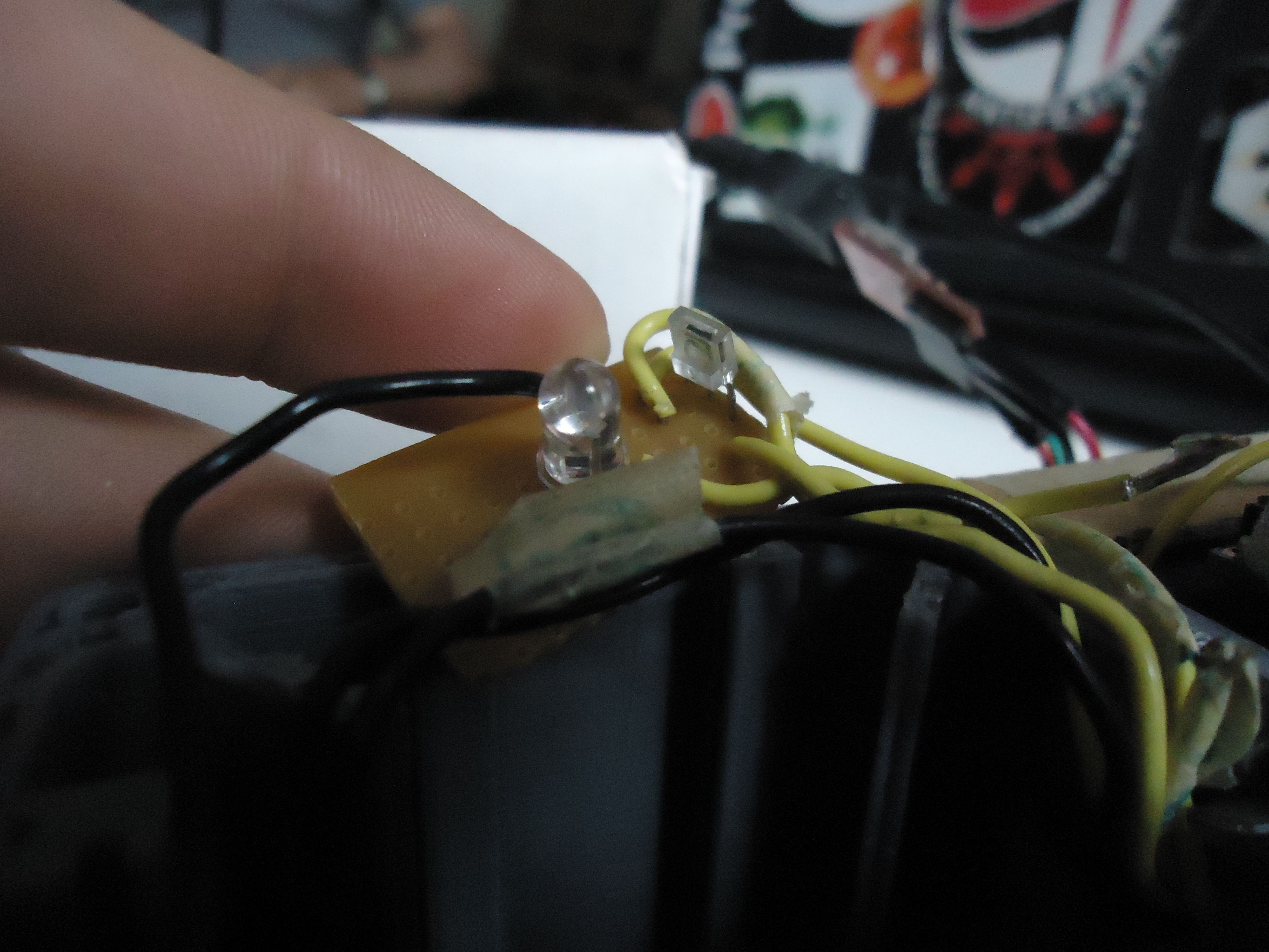
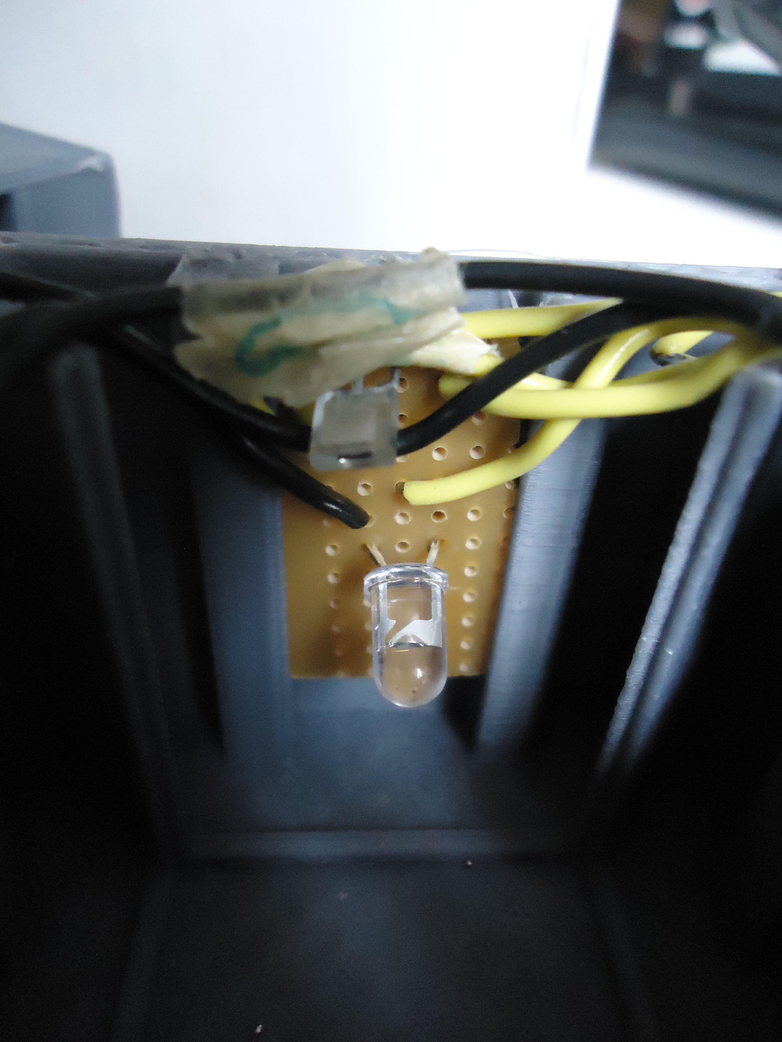
| 09:07, 18 May 2015 | Sensor LED1clear.JPG (file) | 1.15 MB | PCB2. Left: infrared LED. Right: sensor pointing towards the LED. I took this image | 1 | |
| 09:06, 18 May 2015 | Sensor LED1.JPG (file) |  |
1.01 MB | PCB2. Bottom: infrared LED. Top: sensor pointing towards the LED. I took the image. | 1 |