The project aims to bring problems from measurement and control technology closer to a broad audience. The problems are presented in a game-like way, each problem is regarded as a puzzle and after successfully solving a puzzle, the users receive a three-digit code. When all the codes have been collected, they can be used to open a treasure chest at the end, which contains explanations of all the puzzles. This type of puzzle is intended to appeal to a diverse group of people and to stimulate their interest in measurement and control technology or engineering and science in general.
Frequency analysis puzzle[edit | edit source]
The group from this project has contributed a puzzle to the Escape room, which is a game-like frequency analysis in the audio frequency range.

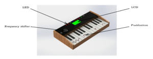
Since in this puzzle signals from the audio area are simulated, it was suitable to use also a housing which reminds of music and audio signals. The figure therefore shows the housing of a synthesizer. There should be different LEDs in the case, which indicate how many tones still have to be detected, which have already been detected and which tone is currently being processed. In order to reproduce the signals, the user has the signal shapes sine, square, triangle and sawtooth at his disposal. The frequencies of the signals can be adjusted via a shifter and a DFT of the signal is shown on the display.
Goal of this article[edit | edit source]
Since it is unlikely that this project will be recreated in its entirety, this article will rather describe the individual construction stages in more detail so that they can be reused for new projects.
Display[edit | edit source]
As mentioned above, in this project a display is installed, in the following will be discussed how this display works, as well as the source code will be explained using examples.
How it works[edit | edit source]

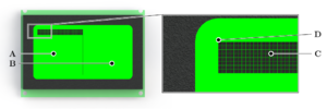
The figure shows the LCD display installed in the device, it is a DEM128068B.[1] It is made up of 2 segments, here marked by the letters A and B. Each of the segments is an independent 64x64 pixel display. The display is always programmed in pixel blocks consisting of 8 pixels in the vertical direction, here marked by the letter C. In the horizontal plane, the display is programmed pixel by pixel, with pixel 0,0 being marked by the letter D. Thus, in the vertical, there are eight rows with sixty-four 8-pixel segments each, which are traversed one after the other. This is done for both display areas A and B, or if only a white or black image is to be created, both display halves can also be addressed simultaneously.
How it is connected[edit | edit source]

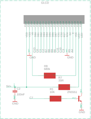
In this project we use a STM32-L476RG[2] microprocessor. The display is connected to it via its GPIO pins. It is also possible to use another microprocessor, but then the source code must be changed. Important for the display is, that at least 13, with adjustable backlight 14, GPIO pins are needed. The resistors and parts used in the circuit diagram have the following functions:
- R8: This resistor controls the contrast of the display and can vary depending on the display. To determine the correct value, a 1M Ohm potentiometer can first be installed here.
- R7: This is the series resistor for the backlight. If the backlight shall not be changeable, another resistor must be inserted here.
- R1: This is the series resistor for the transistor 2N5551. If the transistor is left off, this resistor is also removed.
- 2N5551: This is a NPN transistor, which controls the background lighting of the display by using a PWM. This is optional and the pin LED- of the display can also be connected directly to GND.
The display works very robust, but you should always pay attention that especially the GND connection is very strong, also the data lines should not be too long and go through as few vias as possible. For the STM32 the GPIO used here are configured to "Output Push Pull" with a GPIO output level of "Low" and a maximum speed of "Medium".
The figure shows the different pins. Pins DB0-DB7 correspond to the 8 bits of the display, pins CS1 and CS2 select the display sides. With the pins RST, DI and E write cycles are started and finished, furthermore it is distinguished between a command and a data input for the display. Now it becomes clear why always 8 pixels can be written at the same time, the number corresponds to the number of data bits with which the display and the microcontroller communicate.
Programming[edit | edit source]
The display driver is programmed in C#, in our case in the Cube IDE[3] for the STM32. If all GPIO pins are configured in the microprocessor and the LCD128x64.c, LCD128x64.h and Font_Header.h are included in the program as additional sources, the display can be addressed in the main program. For this it is important to tell the driver which GPIO pins it has to use, for this there is a corresponding initialization.
 #include "LCD128x64.h"
 //LCD Initialize-------------------------------------------------------*/
 lcd128_init_8bits(RS_GPIO_Port, RS_Pin, EN_Pin,
 D0_GPIO_Port, D0_Pin, D1_Pin, D2_Pin, D3_Pin,
 D4_GPIO_Port, D4_Pin, D5_Pin, D6_Pin, D7_Pin,
 CS1_GPIO_Port, CS1_Pin,CS2_Pin,RSTB_Pin); // Initialize Display
after initialization, various functions can be used. The most important ones are:
void LCD128_ClearAll();

void LCD128_BlackOut();

void Center_Text(int y,const char* str,...);

void Allign_Text_Right (int x, int y, const char* str,...);

void Allign_Text_Left (int x, int y, const char* str,...);
the functions "LCD128_BlackOut()" and "LCD128_ClearAll()" clear or fill the whole display, the text functions can output a text on the display. this text can be left, right or center aligned, but not longer than one line. Furthermore the driver contains the options to draw graphs and to show pictures on the display. The file Font_Header.h contains the letter / hex code mappings.
References[edit | edit source]
- ↑ DEM 128064B SBH-PW-N. Rev. 2.1.2. DISPLAY Elektronik GmbH. 2008. DEM128064BSBH-PW-N.pdf.
- ↑ NUCLEO-XXXXRX-P Data brief.DB2196. Rev. 15. STMicroelectronics. 2021. nucleo-l476rg.pdf.
- ↑ STMicroelectronics. STM32CubeIDE. Version 1.9.0. 2. March 2022.Cube IDE.