No edit summary |
No edit summary |
||
| Line 1: | Line 1: | ||
=Hotel Perote | ==Background== | ||
In the summer of 2005, a solar water heating system was designed for Hotel Perote (see document). The system is no longer at Perote. | |||
==System Plans== | ==System Plans== | ||
| Line 12: | Line 13: | ||
The collector will be connected after the filters and installed on the roof. | The collector will be connected after the filters and installed on the roof. | ||
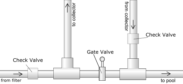
[[Image:SHWH valve setup.png]] | [[Image:SHWH valve setup.png]] | ||
'''Facts:''' | |||
Currently, two pool pumps circulate water through a sand filtration system. | |||
The total volume of the pool is approx 135.5 cubic meters, or 135,500 liters. | |||
The roof of the building on which the solar system will be installed has a height of 26 feet. While the space available on the roof has not been measured from the rooftop, the interior area beneath the roof has been used to estimate the space available for the solar collector. The interior area dimensions are 77 ft by 31 feet. Igancio has requested that the pool be kept at 28 degrees centigrade from October to March. | |||
• Pool surface area | |||
(11.2 by 6.7 meters)+(1.82*pi) = 85 square meters | |||
• Pool volume | |||
The total volume of the pool is approx 112 cubic meters, or 112,000 liters. | |||
'''Predicted temperature change in pool''' | |||
T = (Vc/Fc)(Qp/mc)/(mtsw) | |||
T = change in temperature | |||
Vc = volume of collector | |||
Fc = flow in collector | |||
Qp = heat transfer in pipe (from test) | |||
mc = mass of water which passes through collector | |||
mt = total mass of water | |||
sw = specific heat of water | |||
Qp = mswT | |||
Qp = heat transfer in pipe (from test) | |||
m = mass of water in pipe | |||
sw = specific heat of water | |||
T = change in temperature | |||
'''Solar system plumbing''' | |||
The filters have pumps in them already, which will provide sufficient force to carry the water up to the roof. | |||
'''System design''' | |||
In order to increase ease of testing, the system will include a spigot for obtaining water temperature readings at a point after the water has passed through the collector. A thermometer will also be installed in the pool to take temperature readings there. | |||
Revision as of 04:42, 27 July 2006
Background
In the summer of 2005, a solar water heating system was designed for Hotel Perote (see document). The system is no longer at Perote.
System Plans

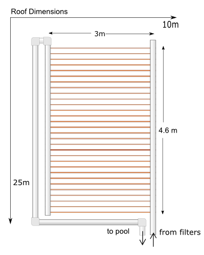
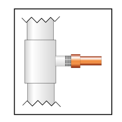
The system will feature a collector consisting of thirty runs of half inch copper pipe, each three meters in length. One and a half inch schedule forty PVC pipes will carry the water to and from the roof. The lengths of half inch copper pipe will be connected to the one and a half inch PVC pipe by tees.
The collector will be connected after the filters and installed on the roof.

Facts:
Currently, two pool pumps circulate water through a sand filtration system. The total volume of the pool is approx 135.5 cubic meters, or 135,500 liters. The roof of the building on which the solar system will be installed has a height of 26 feet. While the space available on the roof has not been measured from the rooftop, the interior area beneath the roof has been used to estimate the space available for the solar collector. The interior area dimensions are 77 ft by 31 feet. Igancio has requested that the pool be kept at 28 degrees centigrade from October to March.
• Pool surface area
(11.2 by 6.7 meters)+(1.82*pi) = 85 square meters
• Pool volume
The total volume of the pool is approx 112 cubic meters, or 112,000 liters.
Predicted temperature change in pool
T = (Vc/Fc)(Qp/mc)/(mtsw)
T = change in temperature Vc = volume of collector Fc = flow in collector Qp = heat transfer in pipe (from test) mc = mass of water which passes through collector mt = total mass of water sw = specific heat of water
Qp = mswT
Qp = heat transfer in pipe (from test) m = mass of water in pipe sw = specific heat of water T = change in temperature
Solar system plumbing
The filters have pumps in them already, which will provide sufficient force to carry the water up to the roof.
System design
In order to increase ease of testing, the system will include a spigot for obtaining water temperature readings at a point after the water has passed through the collector. A thermometer will also be installed in the pool to take temperature readings there.
