Original file (2,652 × 1,442 pixels, file size: 1.2 MB, MIME type: image/png)
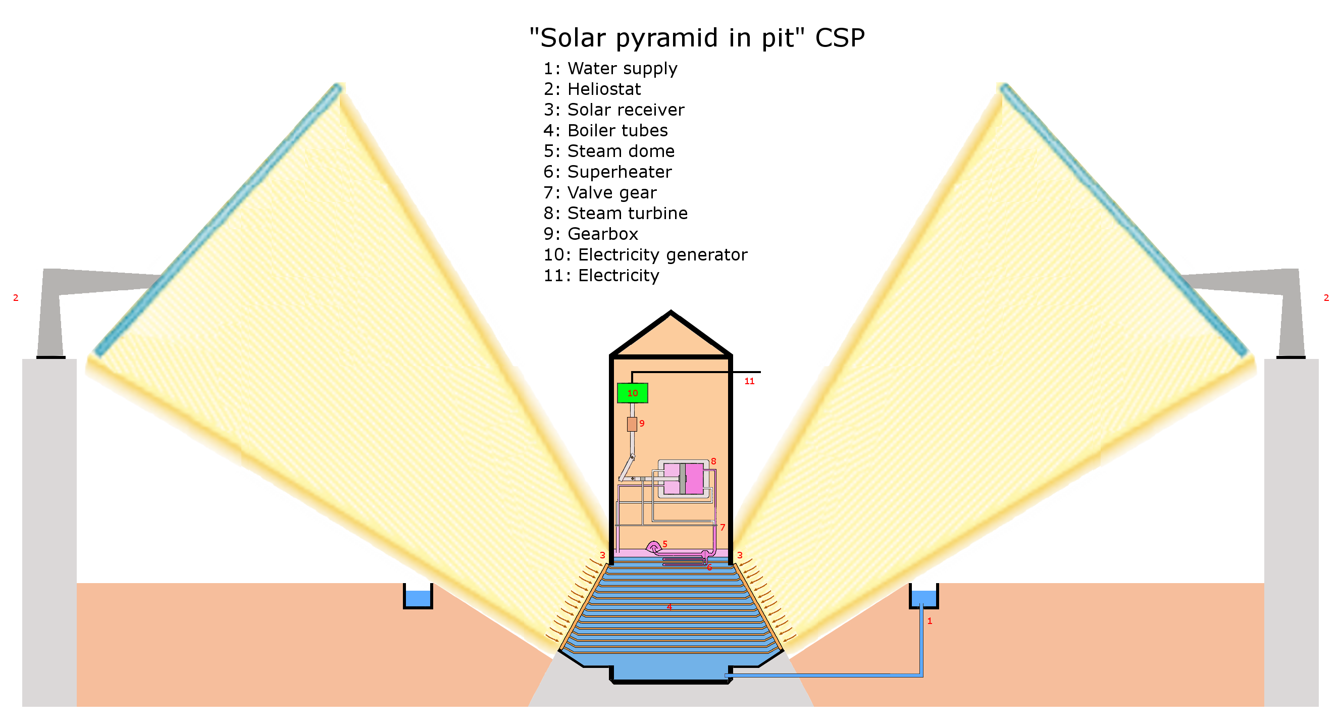
A schematic of a special design of solar power tower: the solar pyramid in pit 1A (design by user:KVDP). Image made, based on following images: http://en.wikipedia.org/wiki/File:Locomotive_fire_tube_boiler_schematic.png , http://web.archive.org/web/20110209173034/http://www.koehler.me.uk:80/animation/loco.htm , http://commons.wikimedia.org/wiki/File:Fire_tube_boiler.gif Note that a possible valve gear (13a) is available at http://commons.wikimedia.org/wiki/File:Steam_engine_valve_gear_plate.png . Also note that there are upper and lower pipes at 13. The upper pipes are both steam inlet pipes, the lower ones are steam outlet pipes. The pipes change function left to right or vice versa every 2 engine cycles. The solar pyramid in pit CSP 1B design is available at http://en.wikipedia.org/wiki/File:Solar_pyramid_in_pit_concentrating_solar_plant_1B.png Note that the water only flows in trough 1 pipe (using a mechanical valve), yet the water itself is transported by a gutter, which flows completely around the pyramid. Only a small section is cementised below the pyramid (grey), the brown color is simply soil. The main advantage of the design is that a lot less source material is needed, since the structure itself is a lot smaller than a regular solar power tower. The heliostats however, still need to be placed on a elevation; the initial intent of this schematic was to use dwellings, in line with a city design being developed at Appropedia. However, it can also be done ie on natural elevations (rocks, ...). Finally, note that the CSP can also be placed upon high-rise buildings, and use heliostats also placed upon these. This is useful for developed cities within (sub)tropical zones. One small advantage is however the need of pumps, either a small power loss is accepted, or an aduquatly sized rainwater harvesting system can solve this.
File history
Click on a date/time to view the file as it appeared at that time.
| Date/Time | Thumbnail | Dimensions | User | Comment | |
|---|---|---|---|---|---|
| current | 08:31, 17 May 2010 | | 2,652 × 1,442 (1.2 MB) | KVDP (talk | contribs) | A schematic of a special design of solar power tower: the solar pyramid in pit 1A (design by user:KVDP). Image made, based on following images: http://en.wikipedia.org/wiki/File:Locomotive_fire_tube_boiler_schematic.png , http://www.koehler.me.uk/animatio |
You cannot overwrite this file.
File usage
There are no pages that use this file.