Original file (1,848 × 1,828 pixels, file size: 389 KB, MIME type: image/jpeg)
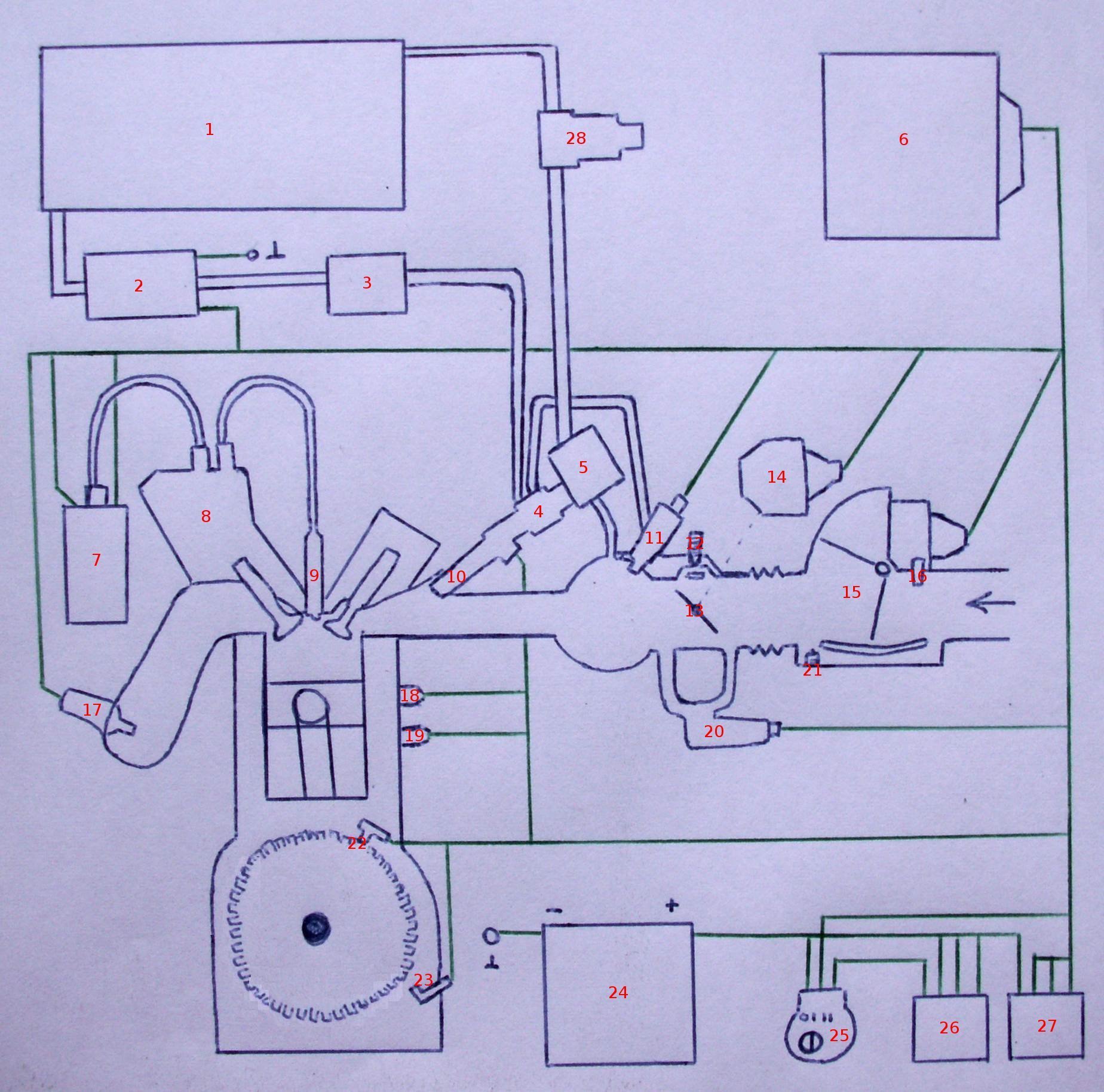
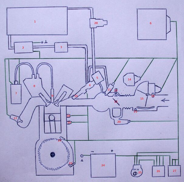
A schematic of a Motronic fuel ignition system (spark-ignition). The schematic was handdrawn, based on an image in the book "Technische leergang: Motorelektronica". Parts: nl --> 1: Brandstoftank 2: Elektrische brandstofpomp 3: Fijnfilter 4: Verdeelbuis 5: Drukregelaar 6: Stuurapparaat 7: Bobine 8: Verdeler 9: Bougie 10: Injector 11: Koude-start-injector 12: Stationairloop-instelschroef 13: Smoorklep 14: Smoorklepschakelaar 15: Luchthoeveelheidsmeter 16: Luchttemperatuurmeter 17: Lambda-sonde 18: Thermotijdschakelaar 19: Motortemperatuuropnemer 20: Extra luchtschuif 21: Stationair mengsel instelschroef 22: Merkteken opnemer 23: Toerental opnemer 24: Batterij 25: Contactslot 26: Hoofdrelais 27: Pomprelais 28: Trillingsdemper
File history
Click on a date/time to view the file as it appeared at that time.
| Date/Time | Thumbnail | Dimensions | User | Comment | |
|---|---|---|---|---|---|
| current | 16:35, 7 August 2010 | | 1,848 × 1,828 (389 KB) | KVDP (talk | contribs) | A schematic of a Motronic fuel ignition system (spark-ignition). The schematic was handdrawn, based on an image in the book "Technische leergang: Motorelektronica". Parts: nl --> 1: Brandstoftank 2: Elektrische brandstofpomp 3: Fijnfilter 4: Verdeelbuis 5 |
You cannot overwrite this file.
File usage
The following file is a duplicate of this file (more details):
- File:Motronic.JPG from Wikimedia Commons
There are no pages that use this file.