Original file (2,400 × 1,964 pixels, file size: 379 KB, MIME type: image/jpeg)
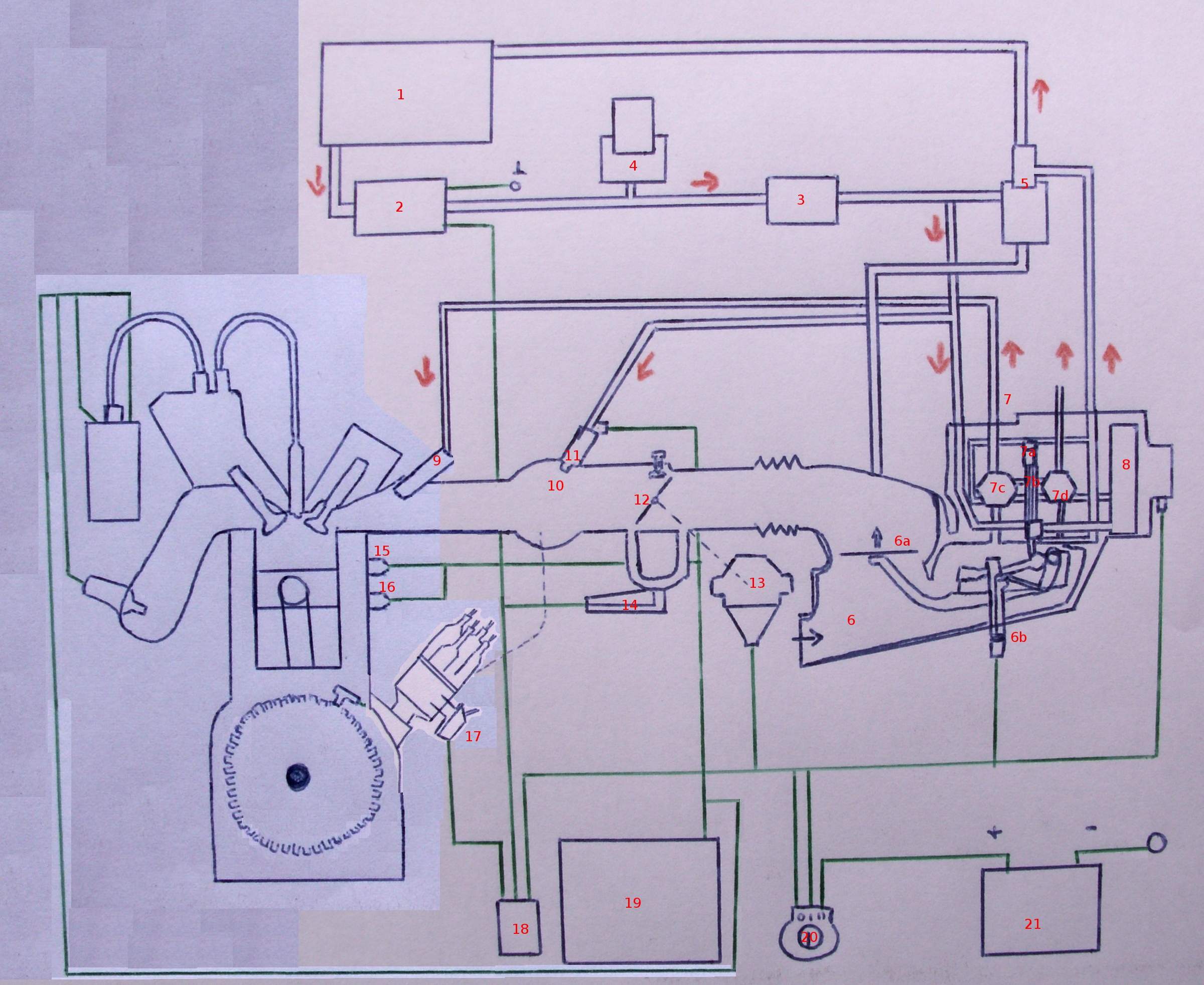
A schematic of a KE-Jetronic fuel ignition system (spark-ignition). The schematic was handdrawn, based on an image in the book "Technische leergang: Motorelektronica".
Parts: nl--> 1: Brandstoftank 2: Elektrische brandstofpomp 3: Fijnfilter 4: Brandstofaccumulator 5: Systeemdrukregelaar 6: luchthoeveelheidsmeter met stuwschijf (6a) en potentiometer (6b) 7: Brandstofregelaar met regelplunjer (7a) en zijn regelkanten (7b) Bovenkamers (7c) en onderkamers (7d) van de verschillende drukkleppen 8: Druksteller 9: Injector 10: Verzamelzuigbuis 11: Koude-start-injector 12: Smoorklep 13: Smoorklepschakelaar 14: Extra luchtschijf 15: Thermotijdschakelaar 16: Motortemperatuuropnemer 17: Verdeler 18: Stuurrelais 19: Stuurapparaat 20: Contactslot 21: Batterij
File history
Click on a date/time to view the file as it appeared at that time.
| Date/Time | Thumbnail | Dimensions | User | Comment | |
|---|---|---|---|---|---|
| current | 16:36, 7 August 2010 | | 2,400 × 1,964 (379 KB) | KVDP (talk | contribs) | A schematic of a KE-Jetronic fuel ignition system (spark-ignition). The schematic was handdrawn, based on an image in the book "Technische leergang: Motorelektronica". Parts: nl--> 1: Brandstoftank 2: Elektrische brandstofpomp 3: Fijnfilter 4: Brandstofa |
You cannot overwrite this file.
File usage
The following file is a duplicate of this file (more details):
- File:KE-Jetronic.JPG from Wikimedia Commons
There are no pages that use this file.