
File:AT alternator brushed engine.jpg
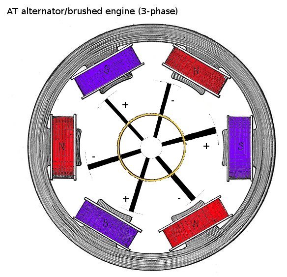
Schematic of the AT alternator/brushed engine. Based on http://commons.wikimedia.org/wiki/File:Rotary_converter,_end_view_(Rankin_Kennedy,_Electrical_Installations,_Vol_II,_1909).jpg
The AT alternator/brushed engine is a long engine, the drawing here shows the front of the engine. A regular brushed engine was preferred so that the need for a motor controller was discarded; also the engine is thus more durable (given that it contains no printed circuit boards; ie motor controller). Regular permanent magnets were included (rather than 2 sets of electromagnets) so that no extra electronics nor additional powersource are needed. The AT alternator is intented to be able to function both as an alternator and as a (brushed) electric engine. It is not intented as the main engine for powerhungry devices (this job is done by the squirrel cage induction engine); instead it is a cheaper (less-efficient) engine, for small devices, and/or applications where a simple electricity generator is required. The red and blue parts are the permanent magnets. These are rectangular and run along the length of the engine. At the inside, there are several coils. These can form electromagnetic poles, or function as general windings (depending on the function, ie engine or alternator). There are 3 sets of poles (3-phase engine).
There are also 3 slip rings; 1 slip ring is shown in the image (center circle; in dark yellow) when used for AC. For DC, a commutator can be used.
File history
Click on a date/time to view the file as it appeared at that time.
| Date/Time | Thumbnail | Dimensions | User | Comment | |
|---|---|---|---|---|---|
| current | 17:43, 3 April 2011 | | 584 × 563 (79 KB) | KVDP (talk | contribs) | added polarity indications when used as engine |
| revert | 17:37, 3 April 2011 |  | 584 × 563 (78 KB) | KVDP (talk | contribs) | Changing design based on Andy Dingley's comments |
| revert | 16:09, 30 March 2011 | 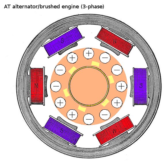 | 584 × 563 (85 KB) | KVDP (talk | contribs) | Cleaned up image; made clear that center part was not entirely open (a small hole is present for the center shaft but this is so small that it seemed pointless to draw it) |
| revert | 16:56, 29 March 2011 | 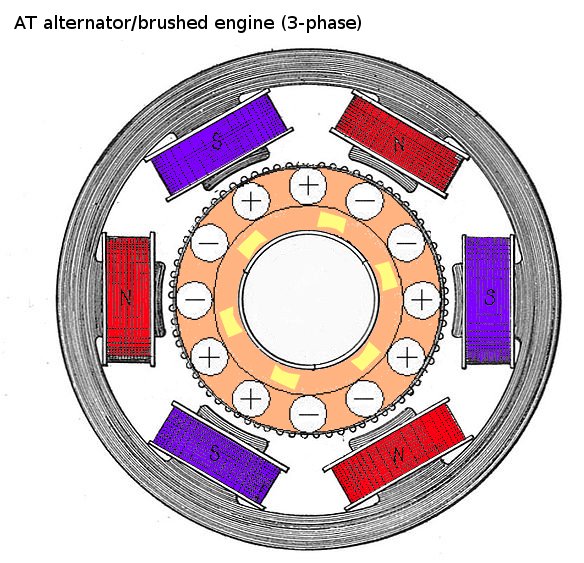 | 584 × 563 (93 KB) | KVDP (talk | contribs) | Schematic of the AT alternator/brushed engine. Based on http://commons.wikimedia.org/wiki/File:Rotary_converter,_end_view_(Rankin_Kennedy,_Electrical_Installations,_Vol_II,_1909).jpg |
You cannot overwrite this file.
File usage
There are no pages that use this file.