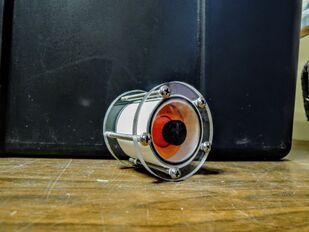
List of Materials[edit | edit source]

- RunCam Robin Camera (with all of the included parts)
- Size #130 O-ring
- 1/4" Cast Acrylic Plexiglass
- Size 1-1/2'' PVC pipe
- 3D-printed Camera Holder G-Code (https://gitlab.com/soar4/soar-camera-holder-3d-print.git)
- Plate Mill G-Code (https://gitlab.com/soar4/soar-camera-mill-g-code.git)
- DC Power Jack Screw Terminal (Male)
- BNC Screw Terminal (Female)
- BNC Video/Power Extension Cable
- Solid Hookup Wiring
- West Systems 2-part epoxy (105 resin and 205 hardener)
- Hot Glue Gun
- Size #8-32 screws (2.5" long)
CNC Milling[edit | edit source]
Use a CNC mill to create the front and back plate for the camera. You'll need to cut-out two pieces of 4" x 4" plexiglass. All G-Codes can be found by pressing the link in the list of materials. In the procedures I will indicate what bit to use for each code. Run the codes in the order stated. Make sure to deburr all edges so they're not sharp after machining the plate.
Backplate Order[edit | edit source]
- oring1 (1/8" milling bit)
- oring2 (1/8" milling bit)
- rectanglecut (1/8" milling bit)
- rectanglecut2 (1/8" milling bit)
- boltpattern (#18 drill bit)
- finalcut (1/8" milling bit)
Frontplate Order[edit | edit source]
- oring1 (1/8" milling bit)
- oring2 (1/8" milling bit)
- boltpattern (#18 drill bit)
- finalcut (1/8" milling bit)
Camera Holder[edit | edit source]
Use the link in the List of Materials to find the G-Code for the camera holder. Download the G-Code and upload it to your 3D printer. Print it with PLA filament.
The link also has the STL file and SCAD file. If you need to change the printer settings or edit the part, use those instead.
Once the camera holder is printed, you may have to sand the edges so it can slide into the PVC tube. Once that's done, do the following steps to attach it to the camera:
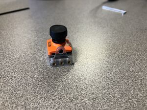
- In the RunCam Robin Camera box, there should be a plastic frame. Slide the plastic frame onto the camera.

- Use the 2 short black screws included with the camera to secure the camera to the plastic frame.
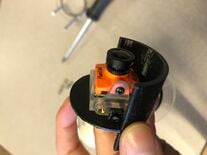
- Slide the camera and plastic frame into the 3D-printed camera holder.
- Line up the middle holes on the plastic frame with the holes on the camera holder.
- Use the longer black screws included with the camera to secure the plastic frame to the camera holder.

PVC Tube[edit | edit source]
Take the PVC tube in the List of Materials and cut it so it's about 1.75" long. Make sure to sand both sides after cutting so it's smooth enough for the O-ring to function properly.
Attaching Terminals[edit | edit source]

Make sure to sand the BNC terminal and DC Power terminal. Sand the part the epoxy will be touching so it has something to grab onto. You want to sand it very roughly.
Hot Glue[edit | edit source]
- Put the BNC terminal in the more square-looking hole in the backplate. Put the DC Power terminal in the other.
- The part of the terminal where wires can be screwed in should be on the O-ring groove side.
- The actual screw should be facing outward.
- There should be space between the screws and the plate so there's room for glue.
- When hot-gluing, you want the terminal to be positioned so it's in the middle of the hole. The terminal should not touch any of the plate. That way there's room for epoxy to go in.
- Gluing Technique: Hold the terminal positioned like in step 5. Put hot-glue on the side with the O-ring groove. Hold the terminal in place until the glue dries. You can glue part of it and wait for it to dry and then glue the rest if it makes it easier.
- Make sure the glue has no holes in it. The purpose of the glue is to hold the epoxy that will be on the other side.
- Make sure the glue isn't too close to the O-ring groove. That won't allow the backplate to sit flat against the PVC tube. If there is glue too close, it can be cut off by using a razor blade.
Epoxy[edit | edit source]
Use West Systems 2-part epoxy (105 resin and 205 hardener). Read the directions on the can in order to mix the epoxy. You'll only have about 10 minutes after mixing the epoxy to put the epoxy where you want it.
IMPORTANT TIP: Make sure to continue to mix the epoxy while you're using it or else it'll hardened too fast and you won't be able to finish the epoxy job.
- Sharpen a piece of wood to put the epoxy onto the backplate. The epoxy should be put on the opposite side of the O-ring groove.
- Try to avoid air bubbles and get rid of them if you find any. Try using a lighter to heat up the bubbles so they go away.
- Set the backplate (epoxy facing up) onto a standing tube so it can sit level while it hardens. It should be hardened in a day.
O-ring Seal without Camera[edit | edit source]
- Put an O-ring in the O-ring groove on each plate.
- Pack the tube full of paper towel.
- Line up the O-rings with the ends of the PVC pipe.
- Put the bolts through the holes in the plates. The head of the bolt should be on the camera side of the PVC pipe (on the frontplate).
- Readjust the O-rings.
- Screw on the nuts with your fingers first.
- Once they're all evenly tight, use a wrench and a screw driver to tighten them. Make sure to tighten them all evenly. You don't want to have different pressures on different parts of the O-ring.
- Check the plates to see if any parts look uneven. That will let you know if the bolts are evenly tightened or not.
- Give each nut one more turn.
Pressure Test #1 (without camera)[edit | edit source]
Pressure test the tube first without the camera inside.
Use SOAR Pressure Tester instructions. Test at the highest psi possible.
- If water leaks in, check these things and re-test:
- Make sure the sides of the PVC pipe are smooth and sanded
- Make sure the bolts are evenly tightened
- Make sure the O-ring groove is the correct dimensions by checking the Parker O-ring Handbook
- Make sure the epoxy isn't letting water in
- Make sure the screw terminals aren't letting water
- If water does not leak in, move onto the next step (wiring).
Wiring[edit | edit source]
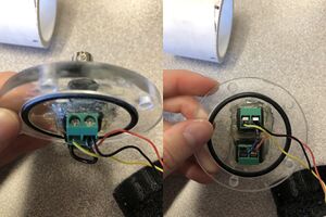
For the screw terminals, when the screws are facing up this is how they go:
Positive Part = Left Side
Negative Part = Right Side
- Take the wire included with the camera and cut one of the white plug-ins off (it won't be needed).
- Cut the wiring down so it's about 3" long.
- Strip the ends of the 3 wires so there's about 1/4" of the inside showing.
- Tin the ends with a soldering iron.
- Cut the solid hookup wiring (idk how long yet), strip the ends, and make sure they're tinned.
- Screw the yellow wire into the positive part of the BNC terminal.
- Screw the red wire into the positive part of the Power terminal.
- Screw the black wire and the solid hookup wire into the negative part of the BNC terminal.
- Screw the other end of the solid hookup wire into the negative part of the Power terminal.
- Plug the white plug-in (that's on the end of the red, black, and yellow wires) into the camera.
O-ring Seal with Camera[edit | edit source]
- Put an O-ring in the O-ring groove on each plate.
- Put the hooked up camera in the camera holder into the PVC pipe.
- Pack some paper towel into the back and front of the camera holder in order to check for leaks.
- Line up the O-rings with the ends of the PVC pipe.
- Put the bolts through the holes in the plates. The head of the bolt should be on the camera side of the PVC pipe (on the frontplate).
- Readjust the O-rings.
- Screw on the nuts with your fingers first.
- Once they're all evenly tight, use a wrench and a screw driver to tighten them. Make sure to tighten them all evenly. You don't want to have different pressures on different parts of the O-ring.
- Check the plates to see if any parts look uneven. That will let you know if the bolts are evenly tightened or not.
- Give each nut one more turn.
Pressure Test #2 (with camera)[edit | edit source]
Pressure test the tube now with the camera inside.
Use SOAR Pressure Tester instructions. Test at the highest psi possible.
- If water leaks in, go back to Pressure Test #1 (without camera).
- If water does not leak, your camera is ready to be used. Don't disassemble the camera unless you run into a problem.
Use Camera[edit | edit source]
- Plug in the BNC Video/Power Extension Cable into the camera.
- Plug the other side into a screen and power.