System requirements[edit | edit source]
The system requirements and specifications to access the OpenSurgiSim software on a computer system (PC) are same as required to access Appropedia pages. Some common specifications are as follows:
- Internet Browser - Google Chrome v84 or higher/Firefox v77 or higher/Safari v11 or higher
- PC RAM - 2GB or higher (available in all PCs and Laptops)
- PC Processor Speed - 1.5 GHz or higher (available in all PCs and Laptops)
- PC Model - Laptop, Workstation, Desktops
- PC Operating System - Any (Windows/MacOS/Ubuntu)
- LAN/Wi-Fi with minimum bandwidth of 100Kbps (we are also developing offline version as well)
Accessing OpenSurgiSim[edit | edit source]

OpenSurgiSim software web software can be accessed on a web‐browser by a trainee surgeon with the web‐address (URL): www.opensurgisim.com .The software asks for login information to let the trainee use the software. For this, the trainee must have signed up for the software. There are 'Login' and 'Signup' buttons on the top left corner of the page. On clicking these buttons, the software redirects to the login and signup pages respectively.

To sign up for the software, trainees have to click on 'Signup' button from the OpenSurgiSim access web‐page which will redirect the trainees to the SignUp page. Here the trainees have to enter name, email address and a unique password, accept the terms and agreements by marking the related checkbox, and finally click on the 'Signup' button. The trainees will get a verification link via email. Once, the trainee surgeon verifies by clicking the verification link, they can then login using the provided email address and password.

To log in the software, trainees have to click on 'Login' button from the OpenSurgiSim access web‐page which will redirect the trainees to the Login page. In the OpenSurgisim login page, trainees can login using the email and password used for signup process. This will redirect the user to the OpenSurgiSim software's home‐page. This will be the trainee surgeon's account and all the data stored via this page after login will strictly belong to the trainee user's account and saved securely on the cloud.

In case the trainees forget the account password, the trainees can access the password recovery page by clicking the hyperlink 'Forgot password' from the OpenSurgiSim login page. On the Forgot password page, trainees have to only add the email of their account and the system will send a new temporary password to the email provided.

In the OpenSurgiSim home page, trainee surgeons can watch a youtube video of how to use the software. They can update and add new account information to the account at the right side panel titled 'Update Account'. After adding/updating the information, trainees have to click on the button 'Save profile info'. Here the trainees can also update the account password by clicking the button 'Change password' at the bottom.
The 'main page' of Deformity Correction Training Module can be accessed by clicking the button "Go To Training Module-1" on the OpenSurgiSim homepage. Currently only Module-1 which is for training on lower-limb bone deformity corrections, is made available to trainees and the other training modules will be made available in near future. There is a 'logout' button on the top left corner, on clicking which the software redirects the trainees back to the login page.

The lower-limb deformity correction training module's main page can be accessed by clicking the button "Go To Training Module-1" on the OpenSurgiSim homepage. The main page has four sub-modules: Planning-guided, Planning - Non guided, Psychomotor-guided, Psychomotor Non-guided and Analysis section. After selecting a particular sub-module (by clicking related buttons at the top), all the surgical cases belonging to that module appear on the left panel in the form of a table (case-list). The list of cases is divided into sections according to the type of cases and arranged into 10 categories. Clicking on each category name expands or contracts the section and shows list of cases in the category as many rows of the table. Each row in every category is one surgical case and sequentially arranged to be followed by the trainee one after the other. There is a preview window on right panel which shows x-rays for the selected case study. There is a clickable button (expand) on the top right corner (second from top) which opens the selected case study in full-screen mode. To go back to the Homepage, there is a button at the top-right corner above 'expand' button.
In case the case studies are not visible after the signup, just click on the button 'Fetch-Cases' on the top and the case-studies will be populated for all the sub-modules.
In case for the first time loading, the page does not show the main-page screen as shown in the picture above (preview image on the right and list of cases on the left), try reloading the page (as we are still optimising the code, sometimes causing disturbances in loading sequence).
In each case-study of the four sub-modules (planning guided, planning non-guided, psychomotor guided and psychomotor non-guided), performance is measured at critical steps, which are used to calculate scores and completion level for that particular case and sub-module for every trainee. In the analysis section, there is an overall performance score and performance analysis is displayed in various analytics formats for training imporvements.
Hardware requirements for Psychomotor Training Sub-Module[edit | edit source]
This Psychomotor-Training Sub-Module is to train surgeons to apply the principles that are learnt in the planning case-studies onto the physical bone models, through various deformity cases. For this, the trainee will need the clinical-tools, physical bone models (as modular bone kit), the training-setup tools, and know-how of the Psychomotor Training Sub-Module setup.
Clinical-tools[edit | edit source]
The clinical tools are required to perform various procedures on the 3D printed bones like drilling onto the bone, resection of bone and placement of external fixator-pins on the bone. The list of various tools required are shown in the figure. How to obtain these tools and their cost estimates are given later in this page.

Modular bone kit[edit | edit source]
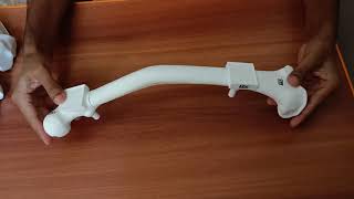
For the psychomotor training, the trainees will obtain the 3D printed modular bone kit, assemble the modular parts of the kit and practice the psycho-motor skills by operating on the assembled bone, under the view of a web-cam connected to a computer running OpenSurgiSim software (capturing the workspace while the training is performed). The modular parts can be assembled to form 10 unique case-studies (2 repetitions for each). A few modular bone parts of the kit has a square shaped marker-holder embedded in them, for placing a specialised augmented-reality (AR) marker. These markers are captured in the webcam view and that helps the OpenSurgiSim software to track the parts of the bone during the psychomotor training. This object tracking helps to give real-time guidance to the trainee and well as assess their surgical performance. The markers can be printed and cut-out on A4 sticker paper, and then pasted on the marker-holder according to the instructions. Following are the resources and instructions to get the modular bone kit and the markers.
Instructions to 3D print the bone kit[edit | edit source]
- Download the 3D model files of the modular bone kit. The modular parts in the kit are of two types: (1) Parts with marker holder embedded on them and (2) Parts without marker holder. The bone modular parts will have specific labels (shown in the figure below) embedded on them to identify them.
- The parts with marker holder can be 3D printed with two alternative methods given in the table below.
- Apart from the modular parts of the bone, there will be other parts to be 3D printed which include 'two bone holders', one 'independent marker-holder' (not attached to a modular bone part) and a 'cut-error measurement tool'.
- Send the 3D files to a 3D printing company in your location who can follow the specifications given in the table below.
| Parts | BoneParts with marker holder | Bone Parts without marker holder | Other parts | |
|---|---|---|---|---|
| Alternative 1
(No need to print markers separately) |
Alternative 2
(Need to print markers separately on sticker paper; Instructions given here) | |||
| Link to download | Download link | Download link | Download link | Download link |
| Printing Specification | 2-3 mm wall thickness and inside hollow | 2-3 mm wall thickness and inside hollow | 2-3 mm wall thickness and inside any lattice structure | 2-3 mm wall thickness and inside hollow |
| Printer and Material Specification | 3D systems SLS printer | HP Jet Fusion Color Printer | 3D systems SLS printer | 3D systems SLS printer |
During the prototype stage of the project we suggest you to email us at vikas@algosurg.com to get the 3D printed bone modular kit with markers attached accurately (we can provide the kit anywhere in the world within a week). This is more preferable until we are experimenting with multiple fabrication techniques to bring the cost down and quality high.
Following table shows the unique parts which will be printed (their labels, pictures and numbers) and obtained as a kit.
| Parts of modular bone kit | Parts belong to Tibia cases | Parts belong to Femur cases | |||||
|---|---|---|---|---|---|---|---|
| Label | Picture | Number | Label | Picture | Numbers | ||
| TA |  |
1 | FA |  |
1 | ||
| TA-2 |  |
2 | FB |  |
1 | ||
| TA-6 |  |
2 | FB-3 |  |
2 | ||
| TB |  |
1 | FB-7 |  |
2 | ||
| TC |  |
1 | FB-10 |  |
2 | ||
| TC-1 |  |
2 | FC |  |
1 | ||
| TC-5 |  |
2 | FD |  |
1 | ||
| TC-9 |  |
2 | FD-4 |  |
2 | ||
| TD |  |
1 | FD-8 |  |
2 | ||
| Other parts | Name | Picture | Numbers |
|---|---|---|---|
| Independent marker holder |  |
1 | |
| Cut-error measurement tool |  |
1 | |
| Bone-holder |  |
2 |
Instructions to assemble the modular parts[edit | edit source]
The modular parts are given specific labels and within each case-study of psychomotor training of OpenSurgiSim, instructions are given to select the right parts according to their labels and assemble them to form the bone model for that case study.
The following table shows how different parts can be assembled into 10 unique bone deformity cases (with twice repetition for practice).
| Case-study No. | Deformity Case study name | ASSEMBLY | Picture of Assembly |
| 1 | Uniapical Tibial Shaft Frontal (UTSF) | TA + TB + TC-1 + TD |  |
| 2 | Uniapical Tibial Juxta-articular Frontal (UTJF) | TA-2 + TB + TC + TD |  |
| 3 | Uniapical Femoral Shaft Frontal (UFSF) | FA + FB-3 + FC + FD |  |
| 4 | Uniapical Femoral Juxta-articular Frontal (UFJF) | FA + FB + FC + FD-4 |  |
| 5 | Uniapical Tibial Shaft Sagittal (UTSS) | TA + TB + TC-5 + TD |  |
| 6 | Uniapical Tibial Juxta-articular Sagittal (UTJS) | TA-6 + TB + TC + TD |  |
| 7 | Uniapical Femoral Shaft Sagittal (UFSS) | FA + FB-7 + FC + FD |  |
| 8 | Uniapical Femoral Juxta-articular Sagittal (UFJS) | FA + FB + FC + FD-8 |  |
| 9 | Uniapical Tibial Rotation (UTR) | TA + TB + TC-9 + TD |  |
| 10 | Uniapical Femoral Rotation (UFR) | FA + FB-10 + FC + FD |  |
The following video (bone assembly for the case 7) will help trainees to understand how to assemble the modular parts to form a bone.
The fabrication method of the modular bone-kit is being continuously iterated and tested by OpenSurgiSim team. It will be changed in future to make it more cost-effective and robust without affecting the training performance.
Instructions to print and place the markers (In case, Alternative 2 was chosen to print the parts with marker holder)[edit | edit source]
It can be noticed that in each assembled bone shown above has two parts with marker holders (where markers need to be pasted). One part belongs to the proximal side of the bone and the other to the distal side. Both will have different pattern markers (Marker-1 and 2) to be pasted on them. Another pattern marker will be pasted on the independent marker holder (both sides).
Hence, there are only three patterns of the markers. Marker-1 for proximal part of the bone, Marker-2 for distal part of the bone and Marker-3 for the independent marker holder. Following is the process of how the markers can be obtained and pasted on the marker holder.
- Download this Markers.pdf file. There are 5 repeated rows of markers (multiple prints for backup). Each row has one Marker-1, one Marker-2 and two Marker-3 (for both sides).
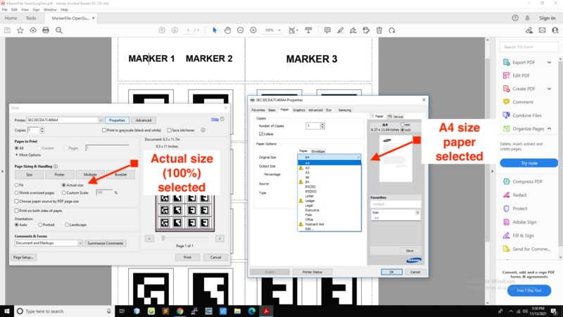
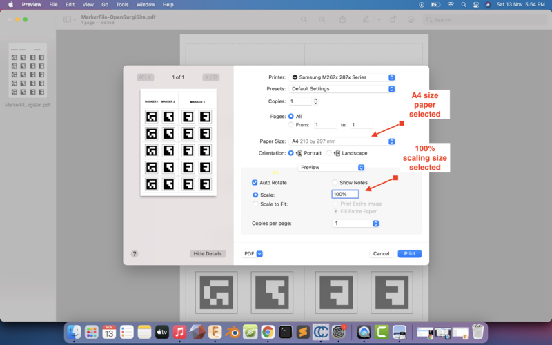
- Print the pdf file in A4 size white sticker paper (Any sticker paper without cut-outs will work like this sticker-paper). Make sure that A4 size paper is selected and printing size is selected as Actual (100%) in the printing settings. This may differ in Windows and Mac hence follow the figures on the right side to set the right settings while printing. This setting will ensure that the marker is printed in its original size as 3.5 cm square.
- Cut-out the square markers (3.5 mm side) from the paper accurately, along the edges of the markers (guidance also given in the marker file).
- Paste the Marker-1 on TB and FA.
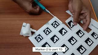
- Paste the Marker-2 on TD and FC.
- To keep the orientation of the marker correct, there is a notch on the marker holder which shows the UP direction of the marker. Keep the upside of the printed cut-out markers towards the notch side of the marker holder.
- Paste the Marker-3 on both sides of the independent marker-holder as well.


The following table shows the parts which need the markers to be pasted on them as well as which marker to be pasted on which part.
| Marker | Part | Pictures | |
|---|---|---|---|
| Marker-1 | TB and FA | |
|
| Marker-2 | TD and FC | |
|
| Marker-3 | Independent marker holder | | |
The following video will help trainees to understand how to cut-out and paste the markers on the marker-holders.
Training-setup tools[edit | edit source]
The Training setup tools is a combination of different electronic devices and physical hardware required for setting up the augmented reality (AR) system and practicing on the physical bone models. It consists of a workspace table, table clamps, webcam, webcam stand, and ring LED light.

The workspace table should be a raised rectangular platform (height from ground - 80 to 100 cm) where a trainee can stand and clearly see and easily work on the the assembled bone cases. The rectangular platform should be large enough to place a computer system on side (left or right) and to have a free 'workspace' area of at least 40 cm x 30 cm in dimensions with white background (for operations on bone model) in front of the trainee. The rectangular platform of the table should have overhang (at least 10 cm) for fitting the two bone-holder clamps on the same side where the trainee will stand and and one webcam stand clamp on one side (wrt the trainee).

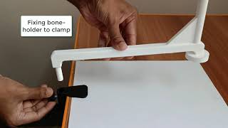
The two 3D printed bone-holders in the assembly are fixed to the Workspace table by two cylindrical clamps. These cylindrical clamps are standard table clamps available in the market which have clamp on one side and a 10 mm diameter cylindrical hole on the other side. The cylindrical part of the bone-holder will go into the cylindrical hole of the clamp. The screw on the side can be used to secure the bone-holder in the clamp. The clamp can be ordered from Amazon website at table-clamp link. Trainees can order any other clamp but it must have 10mm cylindrical hole with a screw for securing the bone-holder 3D part.

Although the trainee can use any webcam which capture videos at 720p (HD quality), we suggest to use the Logitech C270 model. This model is widely available wordwide and it is very cost effective. The camera is required to transmit the view of workspace to the computer system where OpenSurgiSim software is running. This webcam can be ordered from Amazon website at webcam link.

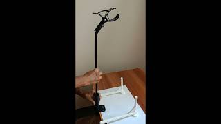
The webcam stand with clamp is required for fixing the webcam at the height of around 60cm from the workspace so that workspace and assembled bones are properly visible in the web camera. It is acceptable if the complete bone is not visible on the camera view however, both the AR markers of the bone assembly should be visible. This stand can be ordered from Amazon website at stand link. Trainees can order any other stand, but make sure that the top part of the stand (where webcam is to be attached) should be at height of 60 cm approximately, so that the Logitech Camera can view the workspace area. Please note that most stands will not have proper attachments to rigidly fix the webcam. In such a case the webcam can only be hanged on the top part of the stand. Trainees can use sticky tapes or rubber bands to secure the camera position if required.

The webcam-based object tracking and the AR-based guidance in OpenSurgiSim software is based on the tracking of the two AR markers of the bone models. This tracking is better in good lighting conditions. Hence, an extra ring LED light with USB is suggested to be attached to the camera stand and connected to the computer system. We suggest this ring LED light which can be ordered from Amazon website at LED link. This light has option for variable brightness and a clamp so that it can be attached to the camera stand. Trainees can order any other LED light but ensure that the lighting is bright white, uniform and it covers the workspace area completely. Also the light should have clamp to fix it to the camera stand.
Estimated Cost of all equipments[edit | edit source]
The training setup and the clinical-tools together would cost around 250 USD. However, most of the tools (like power drill, table etc.) are usually available with the trainee orthopaedic surgeons and in their clinics so the cost of all the tools (setup and clinical) may go down to 150 USD. The LRS external-fixator implant set is also usually available with trainee surgeons who want to perform or improve deformity correction surgeries (the intended users) and hence the cost of tools can further reduce to just 50 USD. In addition, a single LRS implant set can be sterilised and reused (multiple times) in real patient-surgeries as well (especially in LMICs).
The 3D printed bone model kit can be acquired under 700 USD with high quality SLS printing method (preferable for now) and 400 USD with FDM printing method (this will be with an open-source 3D printing machine; still under test) in India. For the current use, we suggest to use SLS method as we are still testing the FDM method. Also, an alternate manufacturing method (casting/molding) is being investigated which will reduce the cost very significantly.
Hence the overall cost to the trainee for this current version of the module can vary from 450 USD to 950 USD. This cost will be brought down to around 250 USD for 20 case-studies once we successfully investigate the new manufacturing method (casting). In case, use want to train on only 4-5 unique case-studies, the cost will be much lower upto 120 USD.
Please note that for this cost the trainee can get trained on 20 (10x2) unique physical bone surgery case studies. Trainee can choose to train on less number of case-studies and reduce the overall cost significantly (since the major cost if of 3D printed bone models).
The following are the estimated costs of all the equipment, tools and models required for the training. Also there are links to order the tools online.
| Sr | Clinical & Technical Equipment | Specification | Cost in USD | Cost in INR | Product Links |
|---|---|---|---|---|---|
| Clinical tools | |||||
| 1 | LRS Rail Fixator implant clamps, T handle and pins Set | Rail fixation system - Adults
Pin diameter: 4.9mm Length: 350mm |
101 | 7500 | Order Rail fixation system - Adults from https://www.pitkar.com/External-fixation-system.html. This company provides external fixators to most of the LMICs including India and Africa. |
| 2 | Hacksaw | Dimensions: 43.3 x 14.2 x 3.9 Centimeters | 7 | 500 | https://www.amazon.in/Bosch-SR-1686-2608003031-Compact-Hacksaw/dp/B07DYBHHM1/ |
| 3 | Power drill | 350 Watts | 25 | 1800 | https://www.amazon.in/Bosch-06011A95F1-GBM-Professional-Drill/dp/B07WCBXXT2 |
| 4 | Drill bits (set of 10) | Diameter: 4.9mm | 11 | 800 | https://www.amazon.in/STANLEY-STA50069B10-HSS-Drill-Pack/dp/B084ZLFVTY/ |
| 5 | Drill Sleeve | Inner diameter: 5mm
Outer diameter: 6mm |
2 | 150 | https://www.indiamart.com/proddetail/5-0mm-locking-drill-sleeve-15670522573.html |
| Training-setup tools | |||||
| 6 | Workspace table | Min length: 80cm
Min width: 50cm |
23 | 1700 | https://www.amazon.in/craft-Purpose-Portable-Foldable-Engineered/dp/B08R7DXX2Z |
| 7 | Web-camera | Logitech C270
720p resolution |
25 | 1900 | https://www.amazon.in/Logitech-C270-HD-Webcam-Black/dp/B008QS9J6Y/?th=1 |
| 8 | Table Clamps (3) | Cylindrical hole with diameter of 10mm and a clamp to fix it to the table | 30 | 2500 | https://www.amazon.com/Microphone-Suspension-Scissor-Adjustable-SUNMON/dp/B093H4C1BW/ |
| 9 | Webcam stand | Scissor arm stand. Each arm length 40cm. Minimum distance of the top part from table surface should be 65cm when extended.
OR Flexible Telescopic Long arm Mount with 360 Degree rotatable clamp. Total length 75cm. |
8
13 |
600
999 |
https://www.amazon.in/dp/B07JGQ9L5B/
https://www.amazon.in/Amkette-Flexi-Phone-Holder-Smartphones/dp/B08QMZJV6Z/ |
| 10 | LED Light (optional) | Ring light, variable brightness, clamp to attach | 10 | 700 | https://www.amazon.in/Tukzer-Flexible-Recording-Photography-Brightness/dp/B096MFN3Q2 |
| Modular bone kit (20 case studies) | |||||
| 1 | 3D printed kit (10 unique cases with double repeatable) | SLS method (Preferable: detailed specifications given above)
Alternate FDM method (Still under testing) |
700
400 |
50000
30000 |
In the prototype stage; please contact the OpenSurgiSim team at vikas@algosurg.com to obtain the bone modular kit. |
How to Set-up Psychomotor Training Sub-Module[edit | edit source]
Steps to setup the module[edit | edit source]
Step 1 - Prepare the training workspace - Trainee has to first prepare the training workspace area on the table. A plain white sheet of total dimension 40 cm x 30 cm can be pasted on the table using a sticky tape. Trainee can use multiple sheets (two A4 sheets side by side - Each sheet has around 30 cm x 20cm ) to get the required dimension. The long side (40cm) of the whitespace will face the front of the trainee while performing the surgery on the bone models. The following picture shows the workspace.

Step 2 - Assembling camera-stand and camera - The goal in this step is to position the camera exactly on the top of the workspace area such that the camera view covers the workspace where the trainees will operate on the assembled bone models and so both the markers of the bone should be visible at a time. For this, the Logitech camera has to be mounted at the height of at least 60cm with the help of the the camera-stand clamped to the table. This can be done in various ways depending on the type of camera stand the trainee has/borrowed. A few important directions given below.
Tightly clamp the camera-stand on one side of the table, and adjust the top part of the stand to hang the webcam to the top of the stand as shown in the video below. The back portion of the Logitech C270 camera can be easily hanged to any camera-stand. Trainees can leave the webcam hanged (as it will be undisturbed during the training) or fix it tightly with a rubber band if required. The distance between the camera and the workspace should be around 60 cm and adjust the camera orientation as well as the camera-stand in such a way that the workspace is visible on the camera view (connect the camera to the computer to check this). The Logitech C270 camera has hinge to adjust the view as shown in the video below.
Step 3 - Assemble the ring LED light (optional) - Attach the clamp of the ring LED light on the camera-stand in such a way that the ring of the light is around the camera lens, as shown in the video above. This is to ensure that the body of the ring LED light do not obstruct the camera view and gives proper lighting to the workspace from the top. This step is completely optional and not required if there is enough lighting on the workspace.
Step 4 - Assembling and positioning the bone - How to assemble the bone from modular parts is given in the previous section here. Follow the modular part codes according to the case-study and assemble them to form the bone. The bone assembly will be placed on the workspace over the bone-holder as shown in the video below. For this, the trainees have to first fix the two table clamps onto the table and the two 3D printed bone holders to the table-clamps, as shown in the video.
If the above assembly is made properly, the trainees will see the bone and its two markers (every bone assembly will have Marker-1 and Marker-2 on proximal and distal portions respectively) properly in the camera view. Both the markers should be visible on the camera view. The markers that are attached to the bone are detected by the software and bone's axes are calculated and displayed automatically. Proper detection of the markers is ensured during the setup-calibration step while performing any psychomotor case-study. The next section describes the setup-calibration method.
Module setup-calibration[edit | edit source]
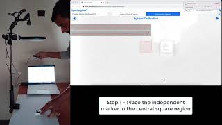
In each case-study, there will be a calibration step (Step-4) which has to be performed well before performing the rest of the steps of psychomotor training on the bone model. Following video will help trainees to understand the step. In this step, the independent square marker is placed in the central region of the workspace shown on the screen (Step-4 of any psychomotor case-study). These instructions are also displayed on the screen. The square region and the instructions maybe in color red if the light brightness and contrast is not sufficient. In such a condition, adjust the brightness of the light falling on the workspace (by turning on or adjusting brightness of the ring LED light, if used) until the square region and the instructions turn green. The following video shows the calibration step.
Risks associated with the Reproducibility of the sub-modules[edit | edit source]
Surgery Planning Sub-Module[edit | edit source]
The surgery planning sub-module is completely digital on the software and hence it will be accessed in the same form everywhere and its algorithms to guide the trainee for planning case-studies, measure the performance parameters and score calculation all will be in the same standard form everywhere. However, in case the internet is not accessible, the software might not load properly, however, the required bandwidth of internet is very low as mentioned in the requirement section.
Psychomotor Training Sub-Module[edit | edit source]
Although it is very easy to obtain the required equipment for psychomotor training, there are a few risks of reproducibility involved.
(1) The 3D printed bone models - In case, the 3D printed bone models are not printed with a good quality as per the machine requirements due to manual errors, quality limitations by the manufacturers or any physical damage, the assembly of bone modules can be improper. This will create errors in the object tracking and hence the performance measurement. Hence, it is advised to 3D print the bone modular kit according to the specifications given and any damage to the parts should be avoided, especially to the parts which are reusable and has markers on them.
(2) The marker size - In one of the alternative method of creating the bone models the markers are printed and cutout in A4 sheet. Proper page size settings and cutting out should be done in order to produce the marker of given size (3.5 cm x 3.5 cm). Any change in the marker size will lead to errors in performance measurements.
(3) The marker position - While sticking the marker to the reusable bone parts proper care should be taken. The marker should be sticked within the boundaries of marker holder. Any significant error in the marker position will lead to errors in performance measurements.
(4) Although wide range of specifications of all the equipment are acceptable, a few specifications should be close to as mentioned, to keep the performance consistent:
- Camera position and resolution - 60 cm from workspace and 720P
- Size of external rail-fixator pin - 4.9 mm
- 3D printing resolution - as given in specifications
Special access for Evaluation[edit | edit source]
Easy access for Demonstration[edit | edit source]
This is only for the convenience of the evaluators of GSTC team and NO ONE ELSE. Others can simply signup for the OpenSurgiSim account to get the demo.
For the demonstration or evaluation purpose, there is no need to signup for a new account of OpenSurgiSim. The evaluator can simply access the software at https://opensurgisim.com/#/ with the following demo account credentials.
UserID - demo@opensurgisim.com
Password - opensurgisim
In this demo account the evaluator can check all the four sub-modules: '''Planning-guided''', '''Planning-Non guided''', '''Psychomotor-guided''', '''Psychomotor Non-guided''' and the '''Analysis''' section to understand the assessment analysis.
Demonstration of Surgery Planning Sub-Module[edit | edit source]
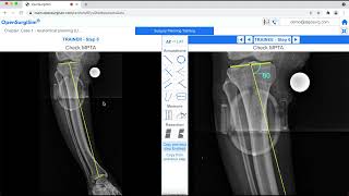
Evaluator can check any case-study in any of the categories (expandable accordion/dropdown). Evaluator may try following the steps of planning of the case-study (guided or non-guided as shown below) and try answering the assessment question to get their final score (its fun!).
Please note that in case for the first-time loading the page does not show the main-page screen as shown in the video above (preview image on the right and list of cases on the left)), try reloading the page (as we are still optimising the code, sometimes causing disturbances in loading sequence).
Demonstration of Psychomotor-Training Sub-Module[edit | edit source]
Alternative 1: Testing single Demo Case-study instead of complete bone-kit[edit | edit source]
In case the evaluator do not want to 3D print the complete kit for testing the psychomotor sub-module, evaluator can still check the case-study named 'Demo-Case' inside the first case-study category (expandable accordion/dropdown) named "Demo-Case Studies". This is the copy of the case-study 1 (Uniapical Tibial Shaft Frontal). Hence for this, evaluator do not need to 3D print the complete bone-kit but only the four bone parts required for the Demo Case and other setup-tools like bone holder etc.
- The 3D printing files for this Demo Case and for some setup-tools can be found here: Demo-Kit.
- The instructions to 3D print this Demo-Kit is same as given here.
- Once the 3D printed bone of the Demo case is obtained along with the other setup parts and tools and the markers, evaluator can assemble the setup.
- The evaluator can then follow the steps in psychomotor training to evaluate the psychomotor training sub-module.
Alternative 2: Testing only AR-guidance and Self-assessment Experience[edit | edit source]
In case the evaluator only want to get experience of the AR-based guidance and object-tracking, we propose another simpler way. Instead of 3D printing the bone parts of Demo-Case, one can 2D print the Demo-Case on sheet of paper to mimic the 3D bone and still get the AR-guidance experience. The 2D printed bone case is the projection of the 3D case and hence it will mimic the surgical process in 2D only, however, the evaluator can get an experience of the AR-based guidance with this simple time-saving method.
- Download this Demo Case.PDF file which has pictures of proximal and distal parts with markers (two sheets) of the Demo-Case bone. This is the projection image of the real 3D case.
- Print the PDF file (two sheets) on A4 size paper (B&W) using the same instructions as given for printing the marker.
- Download and Print the Markers file as per the instructions already given. Cut-out the Marker-3 from the sheet.
- Setup the Logitech C270 web camera as per the Step-2 of setup-instruction already given.
- Connect the camera to PC or Laptop and open OpenSurgiSim software in the browser and login with demo-access credentials given above.
- Open 'Demo Case' from 'Demo-Case Studies' dropdown under Psychomotor-Non-Guided sub-module as shown below.
- Click on 'Expand' button (top right below 'Home' button) to open the case. Since its a non-guided case-study, the case will open directly into Final Assessment Step. Here the evaluator can mimic the performance measurement of bone deformity correction, however, in 2D.

- Place the two sheets one below the other, and place them just below the camera so that the two markers on the bone are visible on the camera view, when checked on the screen, like shown in the figures below.

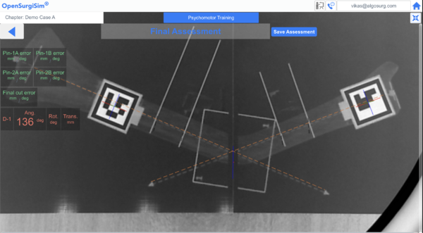

- This will mimic a 3D bone model case and the AR-guidance on the screen will display the deformity angle (D-1 at top-left) at around 136 degrees depending on how the two sheets are aligned. The AR-guidance will also show bone axes in orange dotted lines which will roughly match the axes printed on the sheets. This will be a rough match since the actual bone is supposed to be in 3D for this Demo Case. The 2D sheets are only mimicing the projection of the 3D case.
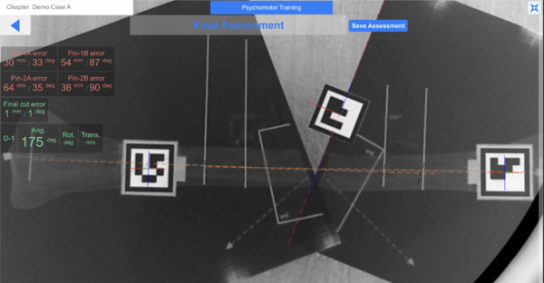
- Now Try to rotate the bottom sheet wrt to the top sheet to mimic the bone correction as shown below. The axes of bones (dotted orange lines) of proximal and distal part of the bone displayed by the AR-guidance will also get align automatically. At the best possible correction achieved by rotating the sheets (making the axes parallel), the deformity angle will change upto 175 degrees as shown in the figure. Remember that the axes are supposed to be in 3D and hence one can not achieve the correction angle of 180 degrees with 2D sheets (even if the axes in 2D sheets and made parallel).

. 
- Now introduce the Marker-3 cutout (on paper only) to the camera view. This will mimic the introduction of independent marker (with Marker-3 pasted on it) to measure cut-error and pin-errors, like what trainee is supposed to do in Final Assessment Step of actual 3D bone case study.
- Place the the Marker-3 near the blue colored bone resection line and one can notice that the Final cut error will reduce to less than 5 mm in position and 5 degree in angle, as shown below. This is mimicing the independent marker placed over the 'cut-error measurement tool' that is placed on the cut surface to measure the bone cutting-error, during the actual training with 3D-printed bone.


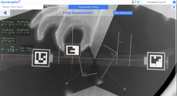
- Now place the the Marker-3 near ideal axes of fixator pins (displayed in camera view as dotted black lines on the bone) for each of the four pins one-by-one and one can notice that the Pin errors will reduce to less than 5 mm in position and less than 5 degree in angle for each pin, if the marker is positioned well. In case, one wants to reduce the error (which is not possible in the Final Assessment step with actual 3D printed bone) the Marker-3 has to be held in oblique way, since the pins are supposed to be in 3D, as shown below. This is like mimicing the placement of marker onto each pin of the fixator in 3D, during the Final Assessment step of the actual training with 3D-printed bone.


- Now click on the button 'Save Assessment' to get the final scores for the case-study.

At the Final Assessment step of any psychomotor case-study with real 3D bone case, the surgery would be already performed and no adjustment could be done on the corrected bone and the errors measurements will show values according to what already performed (one can not make changes to the corrected bone), as shown here. However in the above mentioned paper bone case demonstration, the user has only mimic the final correction and pin position error measurement and using the AR-based guidance, could also achieve very small errors with a score of 10/10. However, this is showcasing how the real-time guidance will work during the surgical steps (step 6 to step 10 here)
We believe that this Paper Bone Case-study Demonstration can give a very good understanding and experience of our AR-based guidance, automatic performance measurement and self-assessment system for the psychomotor sub-module, at very less effort, time and cost to the evaluator.