| Links | Media:40W solar step by step manual.pdf |
|---|
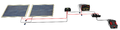
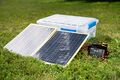
This guide provides instructions on how to create a 40 W solar power array with a 120 Wh energy capacity and the ability to supply power to both DC and AC loads. The total cost to build this system is around $200 USD (depending on sourcing) including the required tools.[1]
You can also download a more aesthetic pdf version of this here: File:40W solar step by step manual.pdf
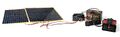
Below are the list of parts, supplies, and tools you will need. Depending on sourcing, you will likely be buying slightly different components. Make sure to read the notes to make sure what you are purchasing will work. This system is purposely designed to be quite adaptable in your component selection.
The following section contains step-by-step instructions on how to assemble this 40 W photovoltaic system.
Connect the panels in parallel with the 10-gauge wires by connecting all three red wires with a 3-way lever nut connector. Note that three red wires include 1 red wire from one panel, 1 red wire from the other panel, and 1 loose red wire you stripped in the previous step. Then repeat the process with the three black wires.
Cut the wire for the blade fuse housing so that there is more wire length on one side than the other. You want to place the fuse housing close to the battery terminal by having a short section of wire. There is no direction for a fuse, so it does not matter which side is shorter, just that one side is.
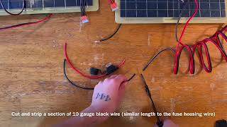
Cut and strip a section of 10 gauge black wire similar in length to the red fuse housing wire. Strip this wire the same as done in a previous step.
Apply 1 yellow spade terminal receptacles to the short end of the red fuse housing wire and another yellow spade terminal receptacle to one end of the newly cut black wire.
To apply the yellow spade terminal receptacles, slide the stripped wire into the receptacle and use the yellow spot on the crimper to firmly press one the receptacle. Check to make sure terminal is on tight.
Place 3-way lever nuts at the bare ends of the black wire and fuse holder wire.
Connect the spade terminal receptacle from the fuse housing wire to the positive blade (red) of the 12 V battery. REMEMBER the battery is the only dangerous thing here. Do not connect the two battery terminals together with anything conductive like metal.
Connect the spade terminal receptacle of the black wire to the negative blade (black) of the 12 V battery.
Cut another pair of 10-guage wire (red and black) and strip it at both ends. The length of the wires depends on the desired distance between the charge controller and the battery.
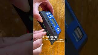
Loosen the battery hatch terminal screws of the charge controller with a small (1/8 inch) flathead screwdriver and insert the newly cut pair of wires with red going to the positive hatch terminal (+), and black going to the negative hatch terminal (-). Close and secure the hatch terminals by tightening the overhead screws.
Connect the open ends of the wires from the charge controller to the 3-way lever nuts attached to the battery, matching red with red and black with black. With this connection established, the LCD screen of the charge controller should turn on. Follow the instructions of the charge controller to set it up for your specific battery type (e.g. in this case LiFePO₄).
If you are using the same battery and charge controller as this how to manual, here are the steps to follow: Press the select key until the battery voltage (batt) is displayed. At this point, press and hold the enter button until the screen flashes with battery types. Cycle through the battery types by pressing the select key until “Li” is displayed, then press enter. Select 12 V as the battery voltage and press enter. In the last option, press select until 14.4 V is shown as the charge voltage, then press and hold the enter key to save and finish the setup.
Connect the bare wires coming from the parallel solar panels (from Step 4) to the solar hatch terminal screws on the charge controller. Refer to the process described above to open and secure the hatch terminals on the charge controller.
Connect the positive (red) wire of the 12 V accessory adapter by inserting it into the corresponding 3-way lever nut attached to the positive (red) wire of the battery (the wire with the fuse holder) and charge controller. For guidance, see the single remaining opening in the lever nut from Step 12 that is connected to the red wires.
Connect the negative (black) wire of the 12 V accessory adapter by inserting it into the corresponding 3-way lever nut attached to the negative (black) wire of the battery and charge controller. For guidance, see the single remaining opening in the lever nut from Step 12 that is connected to the black wires.


Plug the cigar style plug from the inverter into the accessory adapter receptacle for the cigar style plug.
Turn the switch on the accessory adapter to the on position. Turn the switch (if present) on the inverter to the on position.
Once the assembly steps have been completed, the PV system is ready to use. To charge the system, set the panels in an area that receives ample sunlight. To maximize the solar radiation absorbed by the panels, tilt them towards the sun.

To utilize the system to run a DC load via USB (such as to charge a phone) connect the device to the USB port on the 12 V accessory adapter. To power an AC load such as a fan or light fixture, plug the appliance into an outlet on the inverter. In both cases, ensure the switch on the 12 V accessory panel is in the on position. Flip the inverter switch into the on position when utilizing AC loads. You will need to make sure you don't pull more continuous power than the inverter can handle (in this case 200 W, and make sure that your DC accessory plug is rated for that much power as well).
This system can be utilized in a variety of different applications. To understand how long the battery will last, and how quickly it can charge, a low-power and a high-power draw example system is analyzed below. These examples assume a LiFePO₄ battery and very few inefficiencies for simplicity.
An example of a low-power draw system is a 10 W LED light bulb being run continuously. Given enough uninterrupted sunlight, the light can easily be powered without draining the battery due to the 40 W of power supplied by the solar panels. At night, when the solar panels no longer supply power, the light can run off of the battery for almost 12 hours.[15] To fully recharge an empty battery would take about 3 hours with the light off[16] or 4 hours with the light on.[17] A system like this could run with little to no downtime during the summer months.
An example of a high-power draw system is an 80 W box fan. During periods of full sunlight, this system can run continuously for 3 hours[18] before the low voltage disconnect turns off the inverter and shuts down the fan. When no light reaches the solar panels, the system can run for 1.5 hours.[19] Because the power draw is higher than the power supplied by the solar panels, it is not possible to charge the battery while running the fan. With the fan shut off, the solar panels can fully recharge the battery in about 3 hours.[20]
Many intermittent loads can be powered by this system indefinitely.

There are many reasons you might want to build this system. We would love to hear about your personal reasons! Below are reasons you might want to use this guide:
This guide is provided as a free reference. Electricity is dangerous. Batteries have stored energy and can be very dangerous if you short them (i.e., connect the positive and negative terminal with something conductive like metal). You can even hurt yourself with a screwdriver if you try hard enough. Please proceed at your own risk. Appropedia (and any authors) shall not be held responsible for any damages as a result of any activities contained within this guide.
| Authors | Lonny Grafman, Kyle Wolfe |
|---|---|
| License | CC-BY-SA-4.0 |
| Organizations | To Catch the Sun |
| Cite as | Lonny Grafman, Kyle Wolfe (2022–2025). "Step by step 40W solar manual". Appropedia. Retrieved octubre 3, 2026. |