No edit summary |
No edit summary |
||
| Line 19: | Line 19: | ||
<!-- [[Image:Blnd_asst_1_apetsiuk.jpg|400px|right]] --> | <!-- [[Image:Blnd_asst_1_apetsiuk.jpg|400px|right]] --> | ||
<gallery caption="Ultrasonic-based visually impaired person's | <gallery caption="Ultrasonic-based visually impaired person's assistant"> | ||
File:Blnd_asst_01_apetsiuk.jpg|Prototyping stage | File:Blnd_asst_01_apetsiuk.jpg|Prototyping stage | ||
File:Blnd_asst_02_apetsiuk.jpg|Printed parts and soldered electronic components | File:Blnd_asst_02_apetsiuk.jpg|Printed parts and soldered electronic components | ||
| Line 99: | Line 99: | ||
#define trig 7 | #define trig 7 | ||
#define laser 4 | #define laser 4 | ||
long duration, distance; | |||
const int buttonPin = 2; // the number of the pushbutton pin | const int buttonPin = 2; // the number of the pushbutton pin | ||
int buttonState = 0; // variable for reading the pushbutton status | int buttonState = 0; // variable for reading the pushbutton status | ||
| Line 113: | Line 111: | ||
pinMode(echo,INPUT); | pinMode(echo,INPUT); | ||
pinMode(trig,OUTPUT); | pinMode(trig,OUTPUT); | ||
pinMode( | pinMode(buzz,OUTPUT); | ||
pinMode(laser,OUTPUT); | pinMode(laser,OUTPUT); | ||
// initialize the LED pin as an output: | // initialize the LED pin as an output: | ||
pinMode(ledPin, OUTPUT); | pinMode(ledPin, OUTPUT); | ||
| Line 139: | Line 137: | ||
// turn LED on: | // turn LED on: | ||
digitalWrite(ledPin, HIGH); | digitalWrite(ledPin, HIGH); | ||
digitalWrite( | digitalWrite(laser,HIGH); | ||
} else { | } else { | ||
// turn LED off: | // turn LED off: | ||
digitalWrite(ledPin, LOW); | digitalWrite(ledPin, LOW); | ||
digitalWrite( | digitalWrite(laser,LOW); | ||
} | } | ||
| Line 154: | Line 152: | ||
Serial.print(distance); | Serial.print(distance); | ||
Serial.println("cm."); | Serial.println("cm."); | ||
digitalWrite( | digitalWrite(buzz,LOW); | ||
} | } | ||
if(distance<=45 && distance>=1){ | if(distance<=45 && distance>=1){ | ||
// distance in which the bracelet | // distance in which the bracelet makes sound, you can edit according to your need | ||
digitalWrite( | digitalWrite(buzz,HIGH); | ||
digitalWrite( | digitalWrite(laser,HIGH); | ||
Serial.println("Alarm!!!"); | Serial.println("Alarm!!!"); | ||
} | } | ||
| Line 186: | Line 184: | ||
== Technical Specifications and Assembly Instructions== | == Technical Specifications and Assembly Instructions== | ||
# | # First step is to 3D print all the necessary components (estimated printing time: 2.5 hours). | ||
# | # Second step is to put all the electronic components together in the way they illustrated on Figure below (Assembling instruction on he left side). | ||
# | # Third step - solder all the electronics according to the schematic provided on Figure below (Electrical schematic on the right side, estimated soldering time: 3 hours). | ||
# | # Place soldered electronic components into the case as it shown on Figure below (left). | ||
# Connect arduino board to a computer. Run the installed Arduino IDE with the code provided above. | |||
# Upload the code to arduino and make sure it works properly. | |||
# Now we can assemble the cover and screw it to the case. | |||
# Finish assembling by attaching the bracelet to the case. | |||
[[Image:Blnd_asst_assembly_apetsiuk.jpg|550px|Fig 1: Assembling instruction]] | |||
[[Image:Blnd_asst_schematic_apetsiuk.jpg|650px|Fig 2: Electrical schematic]] | |||
<!-- | |||
{{gallery | |||
|width=400 | |||
|height=400 | |||
|lines=1 | |||
|Image:Blnd_asst_assembly_apetsiuk.jpg|Fig. 1: Assembling instruction | |||
|Image:Blnd_asst_schematic_apetsiuk.jpg|Fig. 2: Electrical schematic | |||
}} --> | |||
=== Common Problems and Solutions=== | === Common Problems and Solutions=== | ||
* Solder all the wires with the components being in the place of the approximate final position. It may be complicated to bend soldered wires. | * Solder all the wires with the components being in the place of the approximate final position. It may be complicated to bend soldered wires. | ||
* Test your arduino wired and soldered with all the electronic components before assembling and screwing the cover or bracelet. It would be much easier to arrange all soldered wires or to debugging the arduino in case of any failure. | |||
== Benefited Internet Communities == | == Benefited Internet Communities == | ||
Revision as of 01:29, 7 December 2018
Blind Person's Assistant
THIS PAGE IS UNDER CONSTRUCTION. But it will be ready very soon.
Project developed by Aliaksei_Petsiuk
Template:Statusboxtop Template:Status-design Template:Status-prototype You can help Appropedia by contributing to the next step in this OSAT's status. Template:Boxbottom
Abstract
The given project is a part of Open Source Appropriate Technologies assignment, and it is designed to support visually-impaired people.
As per World Health Organization, there are about 300 million visually-impaired people in the world, 40 millions of them are totally blind. Scientists and engineers are working on systems which would be able to improve the quality of lives of people with the lost vision. A number of modern projects and achievements in this field has been listed in the Reference section.
- Ultrasonic-based visually impaired person's assistant
-
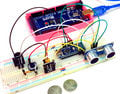
Prototyping stage
-
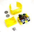
Printed parts and soldered electronic components
-
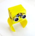
Completed assembly
-
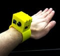
Testing procedures


Bill of Materials
The full list of materials used for the project is provided in the table below.
| Component | Bracelet | Case | Cover | Arduino Nano | Sensor | Buzzed | Laser | 3V Button | Battery | M3x20 Screws | M3x6 Screws | Wires |
|---|---|---|---|---|---|---|---|---|---|---|---|---|
| Image | 
|

|

|

|

|

|

|

|

|

|

|

|
| Quantity | 1 | 1 | 1 | 1 | 1 | 1 | 1 | 1 | 2 | 4 | 4 | 10 |
| Cost/item | $ 0.20 | $ 0.20 | $ 0.20 | $ 3.00 | $ 1.50 | $ 0.30 | $ 0.40 | $ 0.10 | $ 0.50 | $ 0.02 | $ 0.02 | $ 0.01 |
Total cost is $ 5.00.
- 3D source files could be downloaded from here: https://www.thingiverse.com/thing:3265022
- Code for arduino is available at:
- For arduino programming you may need the free open source Arduino IDE which could be downloaded from: https://www.arduino.cc/en/Main/Software
Code for Arduino Board
#define echo 8
#define trig 7
#define laser 4

long duration, distance;

const int buttonPin = 2;     // the number of the pushbutton pin
int buttonState = 0;         // variable for reading the pushbutton status


void setup() {

  Serial.begin(9600);
  pinMode(echo,INPUT);
  pinMode(trig,OUTPUT);
  pinMode(buzz,OUTPUT);
  pinMode(laser,OUTPUT);

  // initialize the LED pin as an output:
  pinMode(ledPin, OUTPUT);
  // initialize the pushbutton pin as an input:
  pinMode(buttonPin, INPUT);
}


void loop() {

  digitalWrite(trig,LOW);
  delayMicroseconds(2);
  digitalWrite(trig,HIGH);
  delayMicroseconds(10);
  digitalWrite(trig,LOW);
  digitalWrite(laser,LOW);

  // read the state of the pushbutton value:
  buttonState = digitalRead(buttonPin);

  // check if the pushbutton is pressed. If it is, the buttonState is HIGH:
  if (buttonState == HIGH) {
    // turn LED on:
    digitalWrite(ledPin, HIGH);
    digitalWrite(laser,HIGH);
  } else {
    // turn LED off:
    digitalWrite(ledPin, LOW);
    digitalWrite(laser,LOW);
  }

  duration=pulseIn(echo,HIGH);
  distance=(duration/(2*29));

  if(distance>=500 || distance<=0){
    Serial.println("____");
  } else {
    Serial.print(distance);
    Serial.println("cm.");
    digitalWrite(buzz,LOW);
  }
  if(distance<=45 && distance>=1){
    // distance in which the bracelet makes sound, you can edit according to your need
    digitalWrite(buzz,HIGH);
    digitalWrite(laser,HIGH);
    Serial.println("Alarm!!!");
  }

  delay(400);
}
Tools needed for fabrication of the OSAT
- MOST Delta RepRap or similar RepRap 3-D printer
- Plastic Filament
- Soldering Iron
- Solder
- Screwdriver
- Hexagon Key
- Breadboard
- Paper Knife
- Tweezers
- Wires Stripper
Skills and Knowledge Necessary to Make the OSAT
All skills you need are at the basic level:
- 3D printing
- 3D Design
- Electronics
- Programming
Technical Specifications and Assembly Instructions
- First step is to 3D print all the necessary components (estimated printing time: 2.5 hours).
- Second step is to put all the electronic components together in the way they illustrated on Figure below (Assembling instruction on he left side).
- Third step - solder all the electronics according to the schematic provided on Figure below (Electrical schematic on the right side, estimated soldering time: 3 hours).
- Place soldered electronic components into the case as it shown on Figure below (left).
- Connect arduino board to a computer. Run the installed Arduino IDE with the code provided above.
- Upload the code to arduino and make sure it works properly.
- Now we can assemble the cover and screw it to the case.
- Finish assembling by attaching the bracelet to the case.


Common Problems and Solutions
- Solder all the wires with the components being in the place of the approximate final position. It may be complicated to bend soldered wires.
- Test your arduino wired and soldered with all the electronic components before assembling and screwing the cover or bracelet. It would be much easier to arrange all soldered wires or to debugging the arduino in case of any failure.
Benefited Internet Communities
- Name and add links to at least 5 using single brackets around [url name]
References
- ↑ Wafa Elmannai and Khaled Elleithy. Sensor-Based Assistive Devices for Visually-Impaired People: Current Status, Challenges, and Future Directions. US National Library of Medicine, National Institutes of Health, Sensors (Basel). 2017 March 2017. Available: https://www.ncbi.nlm.nih.gov/pmc/articles/PMC5375851/
- ↑ Antonio Pereira, et al. Blind Guide: An Ultrasound Sensor-based Body Area Network for Guiding Blind People. Procedia Computer Science, v. 67, 2015, pp. 403-408. Available: https://www.sciencedirect.com/science/article/pii/S1877050915031312
- ↑ Rohit Agarwal, et al. Low cost ultrasonic smart glasses for blind. 2017 8th IEEE Annual Information Technology, Electronics and Mobile Communication Conference (IEMCON). Available: https://ieeexplore.ieee.org/document/8117194