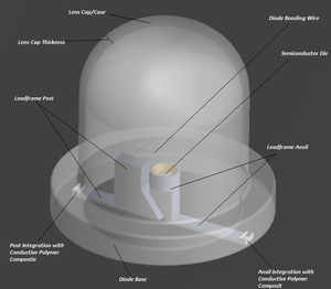
Our idea is to create a self illuminating LED that is powered by ultravoilet and infrared light. The casing is the power source absorbing infrared and UV light, while remaining transparent to visible light.
Benefits of 3D Printing[edit | edit source]
General Benefits[edit | edit source]
- 3D print allows for the construction of a nonuniform geometric shape to be constructed out of semiconductor material.
- Because the Lens Cap of a Diode is not plane construction it is necessary to develop a method that allows us to construct the lens from the bottom up.
- 3D printing allows for the creation of a "pattern" of semiconductor material within the conductive thermoplastic layer that is the primary constituent of the lens.
- In order to produce multiple layers within the cross section of the Diode Lens case, 3D printing is the most efficient method that provides the accuracy and consistincy of placement.
- 3D printing prototypes of designs and ideas allows for an increase in innovation because prototypes can be created in a mattter of hours, feedback can be gathered instantaneously, and designs can be refined numerous times until the prototype is as perfect as possible.
- 3D printing decreases the time it takes a consumer product to reach the market, and allows for "printing on demand"
- One example of this "printing on demand" method has been used by UCreate3D U-Create Websight, who has taken 3D printing to the next level by allowing consumers to customize their own cell phone case with their own images and text.
- 3D printing can also be used to create large quantities of complex designs quickly, and with 3D printers becoming more advanced each year, the capability and speed continues to increase.
- 3D printing can cut down the cost of traditional prototyping and tooling costs.
- 3D printing can help engineers and designers identify flaws in their design relatively early in the design process, and make corrections quickly.
Benefits for Diode Bowsight Application[edit | edit source]
- 3D printing of semiconductor materials allows the size of overall diode to be decreased.
- This is important because the accuracy of a bowsight pin is only as great as the overall size of the pin.
- As the size of the pin increases the resolution of the sight decreases, imagine using a marble as a sight pin... At great distances the pin would be larger than the target that you are trying to hit, then imagine a infitely small sight pin with great brightness, you now have the ability to pick out a location on your target at a greater distance
- This does not only apply to bowsights, this could apply to any sight that is used to target a distant object, the smaller the sight pin the smaller the target can be and at greater distance.
- Also 3D printing could produce these diodes lens cases quicker and with fewer resources decreasing the overall production cost and production time of a sight.
- Also the 3D orientation of the semiconductor material within the diode lens case can be arranged so that only the person targeting an object can be seen, and the need for reflecting phosphorus is eliminated. For a deer hunter, the hunter can see the sight pin in limited light, but the deer cannot. This could eliminate the need of a cover for the diode, or increase the light output of the diode without making it larger.
Literature and Product Research[edit | edit source]
Applications[edit | edit source]
- Our idea is to create a self illuminating LED that is powered by ultravoilet and infrared light. The casing is the power source absorbing infrared and UV light, while remaining transparent to visible light. The anodes and cathodes of the transparent casing are the power source for the diode inside of the casing. The diode generates the light, but the light is visible outside of the casing to the individual. The uses are endless and the scales of the LED's created can be changed from 1.5 mm diameter base for a archer pin to a larger 1 inch diameter for a self illuminating walkway light. We are calling our idea a self illuminating "sticky" diode.
- You could use our device for virtually anything that you would want attach a diode to without need for wireing, circuit, or powering mechanism, and since our design utilizes infrared light it can be powered 24/7. Since our design could produce light 24/7 it can be used to illuminate anything at night, or for other sights that are used on weaponry.
- Most infrared light is given off as thermal radiation, and just about everything gives off some amount of thermal radiation, including the human body.
Understanding the Market[edit | edit source]
Bowsight Selection[edit | edit source]
Types of Bowsights[edit | edit source]
- Fixed Pin Sights
Fixed pin sights are the most common and most popular type of sight SOURCE. Usually comprised of 3 to 5 individual "pins." Each pin can be set to represent various distances with the top tin reprenenting the closest distance, and lower pins representing consecutive longer distances. Once the pins are set the the users desired distances the pins remain fixed.
- Pendulum / Treestand Sights
This type of sight is used mostly by treestand hunters. This is because the design helps to compensate for elevation on downhill shots. When shooting downhill the arrow get a little help from gravity decreasing the amount of drop the the arrow experiences over a distance. The sight has a single pin the is mounted on a pendulum swing, so as the bow is tipped forward the pin swings out and up automatically to compensate for the downward angle of the shot Bowsight Selection Guide
- Moving Pin Sights
This type of sight does not have fixed pins, instead it has multiple preset pins. One of the preset pions is moveable, and can be adjusted before each shot. "The moveable pin sight has a system of brackets, levers, or worm gears that smoothly slide the entire sight housing up and down, so the pin can be adjusted for any distance in only a few seconds. At the rear of the sight bracket, a small adjustable pointer indicated the yardage along a draduated scales of a series of handmade marks on white tape. Each mark represents a known yardage." Bowsight Selection Guide
- 3D Competition Sight
This type of sight is also called a "Target Sight" and are primarily used in archery competitions. This type of sight is the most accurate site available on the market. This sight however still uses a pin that is mounded on a complete system of windage and elevation click-adjustments. Bowsight Selection Guide
Types of Sight Pins[edit | edit source]
- Fiber Optic Sight Pins
A fiber optic sight is similar to a fixed pin sight, the only difference is that fiber optic technology is used to carry light that gets trapped in the fiber optic to a pin that allows the light to escape. This escape point is the tip of the pin on the sight and is used to illuminate the pin in low lighting conditions. Bowsight Selection Guide
- Battery Powered Pins
Uses a battery that powers a secondary light source that is then used to illuminate the pins that are diodes or small lighting filaments. One downsite to this type of pin is that the sight housing must be larger and heavier to accommodate the battery Bowsight Selection Guide
- Chemical Light Pins
Uses a chemical reaction to illuminate the chemical light, however over time this chemical reaction decreases and reduces that light output over time. Bowsight Selection Guide
- Radiactive Pins
Radioactive pins incorporate a small amount of radioactive tritium or phosphorescent powder to illuminate the sight. Tritium can glow softly for up to 10 years without needing a power source. Bowsight Selection Guide
Cost Analysis of Bowsights[edit | edit source]
| Fixed Multipin Sight | Adjustable Pin Sight | Pendulum/Treestand Sight | 3D Competition Sight | |
|---|---|---|---|---|
| Cost Range | $30.00 - $239.00 | $78.00 - $288.00 | $70.00 - $150.00 | $280.00 - $300.00 |
Google Shopping Low and High Prices
- Individual pins can cost from $2.00 to $10.00
- An individual could purchase a basic sight mount for for $30.00 and use our "Sticky Diodes" to create the same effect and utility that a bowsight costing $100 dollars can offer.
Semiconductor Device[edit | edit source]
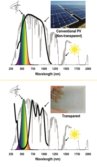
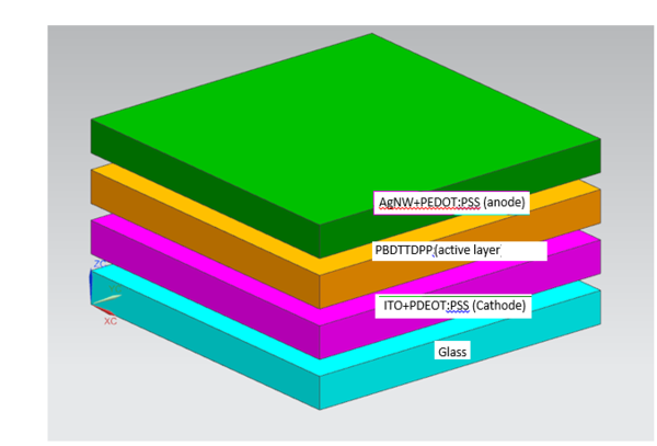
The team has chosen to use a transparent polymer solar cell (PSC) as the material. The device will consist of silver nanowires suspended in a polymer as the anode, an NIR active polymer layer as the semiconductor material and indium tin oxide also suspended in a polymer as the cathode. The photoactive layer transparent to the human eye. Additionally it will allow visible light from the LED the case is powering to escape. The material used as the active layer will exhibit properties as shown in: Transparent Solar Cells (4). Light will be absorbed prior to and after the visible spectrum, but not within. This is the property that makes the material transparent.
The field of PSCs is relatively new, but is opening a whole new world of possibilities. One of the main challenges with transparent PSCs is good conductivity of the electrode is often times compromised when it is made more transparent Transparent Solar Cells (3). Several solution processable conductive materials are being developed to combat this problem. They include: carbon nanotubes, graphene, PEDOT:PSS, and AgNW Transparent Solar Cells (3). Despite the drawbacks power-conversion efficiencies (PCE)as high as 10.6% have been recorded for these up and coming PSCs Transparent Solar Cells (3). The basic architecture of a PSC is a polymer NIR (and sometimes UV) active layer sandwiched between two electrodes. Typically a thin film layer of TiO2 is placed between the active layer and the "top" electrode to prevent damage to the active layer during deposition Transparent Solar Cells (3). An advantage of 3D printing this materials is that the process will not be as violent so the electrode material will not harm the active layer during fabrication. The whole solar cell is fabricated on a protective glass substrate. The purpose of the substrate is two-fold. First to protect the solar cell from the elements and secondly to act as an insulator to keep the device cool.
Design[edit | edit source]
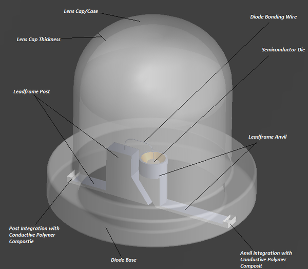
The initial reason we chose to do the light emitting diode.
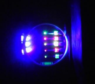
The end product we hope to achieve.
The layering of our semiconductor.
SOFTWARE[edit | edit source]
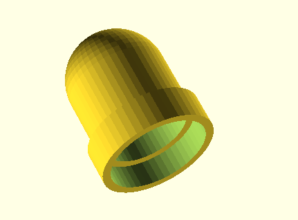
- OpenSCAD OpenSCAD
difference() { translate([0,0,0]) cylinder(1, 1.75, 1.75,$fn=50); translate([0,0,-1]) cylinder(3.75,1.5,1.5,$fn=50); }
difference() { translate([0,0,0.75])
cylinder(2,1.5,1.5,$fn=50); translate([0,0,-1])
cylinder(5,1.25,1.25,$fn=50); }
difference() { translate([0,0,2.75])
sphere(1.5,$fn=50); translate([0,0,2.75])
sphere(1.25,$fn=50); translate([0,0,-1])
cylinder(4,1.25,1.25,$fn=50); }
Power Calculations[edit | edit source]
Area of Photoactive Layer in Lens Cap approx. = 1.7 mm^2

Process Flowchart[edit | edit source]
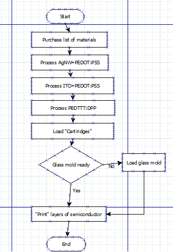
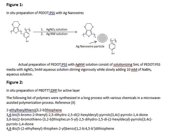
Our process flowchart is simple and when referring to the process portion of each ink refer to in situ figure images below process flowchart.
Materials[edit | edit source]
| Layer (Outer to Inner) | Materials | Viscosity | MSDS |
|---|---|---|---|
| 3 | Indium Tin Oxide In2O3:SnO2 | will be in composite with PEDOT:PSS | In2O3:SnO2 MSDS |
| 1, 3 | PEDOT:PSS | 10 mPa*s | PEDOT:PSS MSDS |
| 2 | PBDTTT:DPP | experimental material - no data | |
| 1 | AgNW Silver Nano Wire | will be in composite with PEDOT:PSS | AgNW MSDS |
Costs[edit | edit source]
| Layer (Outer to Inner) | Casing Materials | Cost/Gram | Amount Required/Single Diode Assembly | Comment | Supplier |
|---|---|---|---|---|---|
| 1, 3 | PEDOT:PSS | $0.42/gram | $1.75*10^-7 | Composite filler for anode and cathode | PEDOT:PSS Supplier |
| 3 | Indium Tin Oxide In2O3:SnO2 | $1.01/gram | $4.08*10^-7 | 90:10 wt% - Cathode material | In2O3:SnO2 Supplier |
| 1 | AgNW Silver Nano Wire | $700/gram | Included in PEDOT:PSS | 99.5% purity - Anode material | AgNW Supplier |
| 2 | PBDTTT:DPP | N/A | $Not Available | Experimental material (not for sale) - NIR active layer | |
| Total | - |
3D Printing Method[edit | edit source]
Construction Development[edit | edit source]
The following procedure lays out the suggested 3D printing method of creating these transparent PSC lens covers, or "sticky diodes". The first obstacle is that the PSC needs a glass substrate, but glass cannot be 3D printed. The printing process would therefore start with small prefabricated glass caps that match the geometry of our lens cover. An inner diameter of 1.5mm would be required. A supplier was not found for these caps specifically, but a supplier such as United Silica could most likely supply the caps. The caps would be placed, opening up on the 3D printer and layers of the device would be deposited onto it. The typical "best" resolution of a RepRap 3D printer is about 100 microns [1] and thus we will be printing 100 micron layers of our three materials on the prefabricated glass casing. Three syringes will be filled with the three aformentioned materials. A layer of the cathode material will be layed down first followed by the NIR active layer and finally by the anode material. The process will be repeated until the glass cap is filled. Small cavities will be printed into the end of the cap to act as connection points for the diode (see above drawing). The outside ring of material would have an outer diameter of 1.5mm matching the inner diameter of the glass cap. The inside diameter of the cap after printing would be 0.9mm. Since many of our materials are relatively new to the market viscosity information is hard to come by. The unknown viscosity values could potentially cause problems with 3D printing of the materials.
In Situ During Processing of "Sticky Diode" Components[edit | edit source]
During the processing individual components XRD is used to identify phases during the polymer synthesis as a quality control process to identify purity of the semiconductor layer and to identify the chemical composition FTIR is used more frequently than most devices as a quality control at the end of each process a solid can be obtained.
Conclusions[edit | edit source]
It is likely that at this point being able to print a transparent solar cell diode lens cap is still science fiction. A few of the real problems that would likely be encountered are as follows
- There may be poor bonding between layers
- Electrons may have a hard time passing though and the device may not be efficient enough to product a significant amount of visible light.
- The affect of 3D printing may take away some of the transparency of the material, due to the ink synthesis and extrusion procedure.
- The tip of the syringe may not be able to fit inside the glass cap to complete the first several layers of the PSC, depending on the type of syringe that is used with the 3D printing device.
- It may not be feasible to extrude the selected materials, but as they are new to the market little data is available on viscosity.
- Along with inherent problems with 3-D printing a Self Emitting Diode Lens Case out of Transparent Solar Cell material the power output of the actual device is so insignificant that this is almost not worthy of pursuing until better band gap potentials are experimentally developed to increase efficiency.
Even with all of the potential cons of the device, the given materials and process would act as a good starting point for the development of LED lens cases for "sticky diodes". Our team has conducted the initial research that may make the production of this device possible in the near future.
References[edit | edit source]
- Light Emiting Diodes
- Transparent Solar Cells (1)
- Transparent Solar Cells (2)
- Solutionizing of TiO2
- Transparent Solar Cells (3)
- Transparent Solar Cells (4)
- PBDTTT-DPP synthesis
- AgNW+PEDOT:PSS synthesis
Contact details[edit | edit source]
| Michael Warhus | Jordan Pontoni | Melissa Wright |
|---|---|---|
| 906-231-0146 | 269-275-7734 | 715-923-9724 |
| mmwarhus@mtu.edu | jgponton@mtu.edu | mjwright@mtu.edu |