Everyday when we look outside, we are in a way measuring the solar resource. We know that a higher irradiance will mean that our skin will feel hotter in the sun, and a lower solar resource will mean we feel cooler. Therefore, if we were trying to take a relative measurement of irradiance, a fairly simple thermal measurement on a constant surface would give a reading proportional to the irradiance in the area. As the solar radiation heats the surface, it will eventually reach an equilibrium temperature where the heat flux leaving through convection, conduction and radiation is the same as the incoming irradiation.
This measurement would still be biased by the ambient temperature and winds, and therefore the accuracy of the relative measurement could be increased by measuring the difference in temperature between a perfect reflector and a perfect absorber, to remove the bias of ambient temperature, and shielding the surface with a glass covering to reduce the effects of wind on the head flux.
What was just described is a simple pyranometer, which is a standard instrument used in the field to measure the available solar resource. However, this instrument will only be able to tell whether there is more or less radiation in the area, but because it is not related back to easily understood physical processes, it is not possible to determine the absolute resource in terms of solar power. In the context of photovoltaic design, the only useful data on solar irradiation is that absolute resource stated in watts(W), usually watts per meter squared.
Therefore, calibration of the unit is required which can relate the temperature differences measured to absolute solar irradiation. This is a complex procedure, and a brief discussion of the history of these measurements is required to understand how we got to the measurements we use today.
If we had no eyes we should still know of the sun by the feeling of warmth.
The following tutorial will cover topics related to the theory and hardware used to measure the available solar resource at a site, and methods for translating this radiation onto the inclined plane of a PV panel.
A Brief History of solar radiation measurement[edit | edit source]
If the observation of the amount of heat the sun
sends the earth is among the most important and diffi-
cult in astronomical physics, it may also be termed the
fundamental problem of meteorology, nearly all of
whose phenomena would become predictable, if we knew
both the original quantity and kind of this heat..." Dr. Samuel Pierpont
Langley, third Secretary of the Smithsonian Institution
The modern measurement of solar radiation in North America was originally aimed at better understanding the relationship between the sun and the earth's climate, and was pioneered by both the Smithsonian institution and the national geographic society, with the goal of determining the "solar constant" or the amount of energy available at the edge of our atmosphere. The first studies were performed with a device known as a Bolometer, invented by Samuel Pierpont Langley, the future secretary of the Smithsonian Institution in 1878. This was an extremely sensitive device for measuring temperatures, accurate to 0.00001C, and has the honour of supposedly able to measure the thermal radiation of a cow at a quarter mile.[1] The bolometer was used with a prism which split the light into its spectrum. The rise in temperature was measured as a current shown with a galvanometer, an extremely precise device for measuring current, which consisted of a needle made from a strand of quartz 2/25,000 inch in diameter and 15 centimeters long onto which a mirror only 1/25 inch square and 2/1000 inch thick is placed. As an electrical current is passed through this galvometer, this tiny thread will rotate on a pivot, also rotating the mirror. The mirror directs a beam of light onto a photosensitive sheet of paper, and the amount of deflection from home is proportional to the current. It is in this way that extremely sensitive measurements of the solar spectrum were originally made.[2]
The pyroheliometer[edit | edit source]
The pyroheliometer is a device designed to measure the total energy available from the entire solar spectrum. The original pyroheliometer was designed in 1837 by Claude Pouillet which was a simple but crude instrument based on water calorimetry which eventually was proven to be inconsistent and inaccurate. Following this, an instrument was made in 1887 by Klaus Angstrom called the compensation pyroheliometer. This instrument consisted of two thin magnesium strips in thermally identical chambers. One chamber was open to the sunlight, and the other was closed by a shutter, and heated electrically by a known power. When the temperature in both chambers agreed, a measurement of the electrical power was taken. The shutter was then reversed, and another measurement was made. By comparing these two measurements, a determination of the total irradiation was made[3]
This instrument was considered to be an early standard instrument, and formed the basis for the Angstrom Scale (denoted AS05), founded in 1905.
Slightly after the development of the Angstrom compensation device, another device was developed independently at the Smithsonian institution by Charles Abbott, as they were unable to obtain an angstrom device.[4] This device was known as the silver disk pyroheliometer, and consisted of a long tube with a shutter at one end, and a thin stip of silver painted black at the other. The silver strip is in thermal contact with a bulb thermometer. To measure the intensity of solar radiation, the shutter is closed for 100 seconds and the temperature drop is noted, the shutter is then opened again and the temperature rise after 100 seconds is noted, finally the shutter is closed a final time and the temperature drop after 100 seconds is noted.
In order to correlate these temperature changes with the actual power being input into the system, a very complex analysis of this device would be required. Instead, this device was callibrated using another instrument, the water flow pyroheliometer. Essentially, light was admitted in the same way as the silver disc pyranometer, and the beam of light is directed onto a conical receiver, which is assumed to absorb 97% of incoming radiation. Because of the conical shape of the receiver, the reflected light is directed to the walls of the tube, which are also blackened and absorb 97% of the incident light for each time it is reflected. In this way, it is assumed that nearly all of the incoming radiation is absorbed. Water at a constant flow rate and temperature is then allowed to flow in passages in good thermal contact with the walls of the chamber. The rise in temperature at steady state can be measured and from this an exact determination of the incoming power can be determined.[5]
The combination of these two instruments formed the Smithsonian scale, denoted SS13 in 1913.
Radiometric Scale[edit | edit source]
In 1956 these two scales were amalgamated to form the International Pyroheliometric Scale, IPS56 which applied corrections to readings made with instruments from either scale.
The most recent radiometric scale is the World Radiometric Reference, which is composed of 15 absolute cavity radiometers, each from different manufacturers and tested continually to ensure no drift of malfunctions occur over time. These instruments make up the World Standard Group (WSG), which is located and maintained at the World Radiation Centre in Davos, Switzerland. {WMO PAPER} This is the current standard to which all measurement devices are compared, and has an estimated accuracy of 0.3% and precision of 0.1%.[6]
Primary Standard instruments[edit | edit source]
Each country has a separate absolute cavity instrument which resides in its country, but which is re-calibrated every five years at the WSG in Davos. These instruments are known as Primary standard instruments, and are used primarily to calibrate commercial pyranometers.
Measurement of solar resource for PV applications[edit | edit source]
The measurement of the solar resource for PV applications is vital for making rational decisions on the size, type, and general design of a PV array. The accuracy required varies widely on the proposed application of the data, and thus there is a broad range of available instruments. The purpose of this section is to provide a better understanding of pyranometer function and applications, and it is recommended to first read this for a comprehensive overview of the solar resource and solar angles.
Before entering into a discussion on pyranometers, some terms to define radiation types should be clarified:
Beam Radiation: Beam radiation is the radiation which exists within a 6° cone of the solar disk. This definition comes from the measurements made by most standard pyroheliometers which have a 5° field of view.
Diffuse radiation: Diffuse radiation is that radiation which is reflected from the sun and does not necessarily come from the direction of the sun. The easiest way to understand diffuse radiation is to consider your shadow, you are still able to see the ground beneath your shadow, but there is a noticeable difference in light between your shadow and the surrounding area. The light illuminating the area under your shadow is the diffuse radiation, and the difference in illumination is the beam radiation
Global radiation: The total radiation in an area, the sum of diffuse and beam radiation.
Isotropic radiation: Radiation which is assumed to have an equal value in all directions. Diffuse radiation is more isotropic than beam radiation
Commercial devices for measuring solar radiation for PV applications[edit | edit source]
There are essentially two categories of devices used for measuring the solar resource: pyranometers and pyroheliometers
Pyranometer
The most common instrument used in PV applications, there are two general types thermal and photovoltaic. A photovoltaic sensor is essentially an extremely accurate solar cell which outputs an electrical current proportional to the solar radiation, and this electrical current is calibrated to represent the solar irradiation in W/m2. This type of sensor in generally low cost, but the largest problem is that a photovoltaic panel does not have a constant response across all wavelengths. Therefore, if the spectrum being seen by the detector is different from the one it is calibrated for (typically the AM 1.5 solar spectrum) a significant error will be introduced.
The second type of pyranometer is a thermal pyranometer. This device essentially measures the difference in temperature between a perfect absorber and perfect reflector, the difference in temperature is proportional to the solar radiation. This style of pyranometer has a constant output over all wavelengths of the standard solar spectrum.
Pyroheliometer
The pyroheliometer is an extremely accurate device which measures beam and circumsolar radiation, usually within a 5° cone of the solar disk.
Device Quality[edit | edit source]
There are three quality classes of pyranometer which are defined by ISO 9060
Secondary Standard Instruments
These instruments are the highest grade of commercial pyranometer available, and are compared directly to primary standard devices, according to ISO 9060 and ISO 9846. They typically have error in the range of 1%-3%
First Class instruments
A first class instrument has less accuracy than a secondary standard instrument, and generally has an accuracy of 5%-8%.
Second Class instruments
Second class instruments are of a lower quality than first class instruments, and have poorer accuracy and stability.
Pyranometer specifications[edit | edit source]
The following parameters are used to classify pyranometers, and some typical significances of each parameter are outlined
| Parameter | Typical values for
Secondary Standard |
Typical values for
Second Class |
Definition | Applications |
|---|---|---|---|---|
| Response time | 5s | 18s | Time for the sensor to register a change in radiation | Inverter Studies, Performance Ratio determination |
| Zero Offsets-Thermal radiation | <3W/m2 | <15W/m2 | Drift of sensor zero point due to changes in radiation | General accuracy, Efficiency calculations |
| Zero Offsets-Temperature | <1W/m2 | <4W/m2 | Drift of sensor zero point due to ambient temperature | General accuracy, Efficiency calculations |
| Non-Stability | <0.5% | <1% | Yearly drift of calibration | Determination of required calibration intervals |
| Directional Error | <5W/m2 | <20W/m2 | Error associated to the angle of incidence of beam radiation (usually given at 80° and 1000 W/m2) | Measurements occuring at sunrise or sunset |
| Tilt Error | <0.2% | <1% | Error associated with mounting a pyranometer on an angle | Measurements of in plane irradiation for solar panels |
Additional equipment for solar measurement[edit | edit source]
Shade rings
Shading rings block direct beam radiation from hitting the pyranometer sensor, and thus measures the diffuse component of radiation. The use of two pyranometers, one shaded and one not, allows the measurement of global, diffuse and beam radiation (beam=global-diffuse). The use of a shade ring requires weekly physical adjustments. A solar tracker can also be used, which automatically places a shading sphere between the pyranometer and the sun, shading it for the entire day without the need for physical adjustment.
Ventilators
A ventilator keeps the pyranometer at a constant temperature, and helps keep the glass dome clear from dew, frost and snow. In addition, it reduces the effects of temperature drift.
Choosing a pyranometer[edit | edit source]
There are many factors to consider when selecting a pyranometer, some things to consider are
- Application of the data: For general interest, PR, or rough site determination purposes, a second class instrument might be acceptable. However, the errors in this unit may be as much as 10%, which could lead to significant differences in actual PV yield. For large scale developments, a higher standard unit should be used to provide accurate yield analysis. For panel efficiency testing, research and extremely large developments, secondary standard units should be used.
- Costs: A second class pyranometer can cost as little as $600, whereas the highest quality of secondary standard instrument costs up to $10,000. However, when developing a business case for a 10MW plant, 1% error in yield prediction can cost in the order of $55,000 which easily covers the cost of more accurate equipment.
- Mounting method: If a pyranometer is to be mounted in an inclined position, the tilt error should be considered. If a silicon photovoltaic sensor is being used, it should be noted that the reflected component of the radiation will effect the calibration of this sensor, producing large errors
- Diffuse ratio of radiation: The diffuse ratio refers to the fraction of radiation which can be considered to be diffuse, and not eliminating from a specific direction. For a stationary system, this ratio is not of critical importance. However, if considering the use of a tracking system it is very important to know the diffuse ratio of the radiation. If it is high, then the relative gain from a tracking system will not be as great as if all the radiation was beam radiation. Therefore, a two pyranometer system with a shading ring should be used.
There have been many reports on the relative accuracy of pyranometers, one significant study was produced by NREL and characterizes many commercial pyranometers in an independent test bed. It can be accessed at: http://www.nrel.gov/docs/fy09osti/44627.pdf|NREL Paper
Determination of in-plane radiation[edit | edit source]
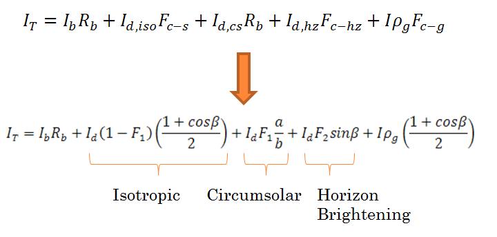
Most measurements of solar resource are measured at horizontal, however a typical PV panel will be at an angle to the horizontal, which means that the solar radiation on this plane will be different than this horizontal value. This is the reason that it is important to angle a PV array at the optimal angle to the sun to maximize yield. In order to determine in-plane radiation, the components of radiation incident on a panel should be investigated [7]:
Where the diffuse components can be defined as:
Isotropic: Can be considered to be emanating uniformly from the sky.
Circumsolar: Forward scattered light.
Horizon Brightening: Radiation on the fringes of the horizon.
Ground Reflected: Also referred to as albedo.
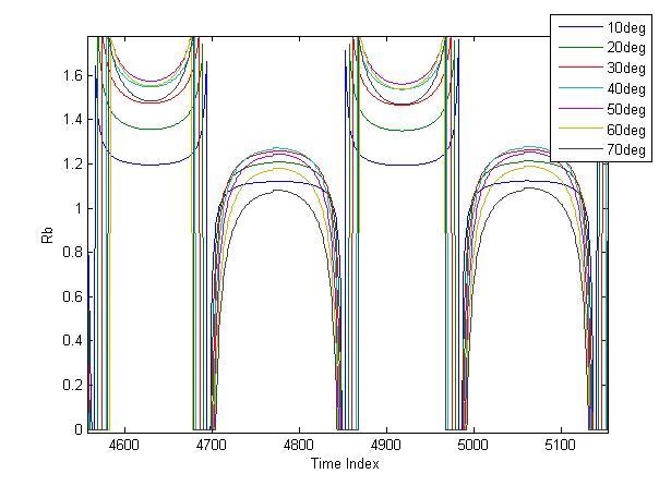
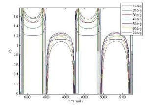
Translating the beam radiation onto the plane of the panels is a fairly straightforward matter of geometry. The factor Rb is the ratio of in plane beam to horizontal beam (Ib), and is given by:
As an example, curves of Rb over 2 days for angles of 10 to 70 degrees can be seen below
The treatment of the diffuse radiation is more complex, and several models have been put forward to account for it.
Isotropic model[edit | edit source]
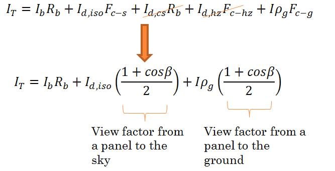
This is the simplest model, and also the most inaccurate. The essential assumption in this model is to assume that all diffuse radiation is isotropic, and the equation can be reduced:
Hay and Davies[edit | edit source]
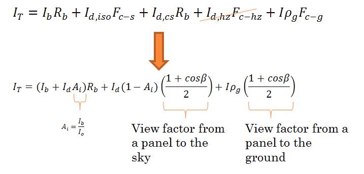
This model uses the anisotropy index, Ai, which is the ratio of beam to global radiation and considers forward scattered radiation:
Perez[edit | edit source]
One of the most complex and accurate models for determining total in-plane irradiation, this model uses multiple empirical relations to create a very accurate representation:[8]
Correlations if only horizontal global radiation is available[edit | edit source]
Sometimes, only one pyranometer has been used, and only global radiation information is available. In this case, there are multiple correlations which allow the average beam and diffuse radiation to be determined. These correlations are mostly of a similar form, and are relations between the ratio of global to extraterrestrial radiation (Kt) and the ratio of diffuse to total radiation.
See also[edit | edit source]
- A Review of the Effects of Haze on Solar Photovoltaic Performance
- Snow Losses for Photovoltaic Systems: Validating the Marion and Townsend Models
- The Impact of Snow Losses on Solar Photovoltaic Systems in North America in the Future
References[edit | edit source]
- ↑ (High Altitude Observatory, (2005).Samuel P. Langley Biography. University Corporation for Atmospheric Research, Accessed at: http://web.archive.org/web/20120215035056/http://www.hao.ucar.edu/education/bios/langley.html [July 3,2010]
- ↑ Abbot, Charles Greeley (1929). Sun and the Welfare of Man. Smithsonian Institution Series, USA.
- ↑ Frohlich,C. (1991) History of Solar Radiometry and the World Radiometric Reference. Metrologia 28 111
- ↑ Abbot, C and Aldirch, L. (1911). The Pyroheliometric Scale. Astrophysical Journal, vol. 33, p.125
- ↑ Abbot, Charles Greeley (1929). Sun and the Welfare of Man. Smithsonian Institution Series, USA.
- ↑ Frohlich,C. (1991) History of Solar Radiometry and the World Radiometric Reference. Metrologia 28 111
- ↑ Duffy,J and Beckman, W (1991). Solar Engineering of Thermal Processes. John Wiley & Sons Inc, USA.
- ↑ Perez, R., Ineichen, P., Seals, R., Michalsky, J., Stewart, R. (1990). "Modeling Daylight Availability and Irradiance Components from Direct and Global Irradiance." Solar Energy, 44(5), 271-289.


