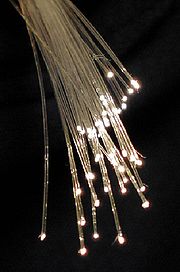
Optical FibersW are long fibers consisting of either glass or plastic. They are used to transmit light signals over long distances at high rates of transfer.
Optical fibers have replaced the conventional use of metal wiring to transmit information in areas where the benefits of fiber optics greatly out weigh those of conventional means.
Some benefits of using optical cables to transmit information is that they use light waves in stead of electronic pulses and are therefore immune to electromagnetic fields[1][2]
Applications[edit | edit source]
- Fiber optic cables are used today as a telecommunication and networking medium. They offer a means of physically attaching information ports with flexible, high speed, reliable transmission lines. The low attenuation rate in fiber optics provides a low transfer error rate. In 2001, optic fibers were recorded to have transfer rates of up to 40 Gb/s per fiber.[3]
- Facilities, such as power generating stations, create large electromagnetic fields that disrupt information that is transmitted in metal cables. Therefore fiber optics, being immune to such fields, can be used reliably in these situations.
- Measurement Sensors can use fiber optics to measure strainW, temperature and pressure by modulating intensity of light, phase changesW, polarizationW, wavelengthW and transmission time of light.
- Fiber optics are used to transmit visibleW light from one source to another.
- This is used in medical procedures as many operations are conducted in very small areas requiring very direct focused lights without the limitations of line of sight required by conventional light sources.
- Light can also be rerouted from a collector on the exterior of a building and guided inside to locations that do not receive natural sunlight normally.
- Light can be transmitted for the purposed of aesthetics in sign displays or festive decorations in commercial products.
Background Information[edit | edit source]
Apparatus[edit | edit source]
Fiber optic fibers are dielectric waveguidesW that take advantage of Total Internal ReflectionW to transmit light. A central core made of SilicaW (SiO2) and GermaniaW, which ranges in diameter from 8um to 63 um.[4][5] This is surrounded by a Silica sleave called the cladding.
The core and the cladding have different refractive indicies
Theory[edit | edit source]
Total Internal Reflection allows the fiber to reflect on the cladding boundary and contain the light within the core. From this, the optic fiber acts as a waveguide.
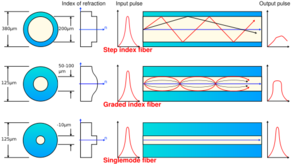
Total Internal Reflection occurs due to the differences in Refractive Indices between the core and the cladding of the fiber. The core always has a higher refractive index than the cladding because this will cause light beams to reflect inwardly and continue to travel from one end of the fiber to the other. The refractive indexW is kept low as higher indices retard the speed of light, thus slowing information transfer rates.
Chemical Reactions[edit | edit source]
The reactions that occur in the fabrication of optical fibers are found in the formation of the preform as described in the next section.
The reactions that occur are as follows:
SiCl4 + O2 -> SiO2 + 2Cl2
GeCl4 + O2 -> GeO2 + 2Cl2
Process[edit | edit source]
Preform Manufacturing[edit | edit source]
A Preform is a cylindrical piece of material commonly measuring 1 meter long and 10 centimeters in diameter.
Modified Chemical Vapor Depos (MCVD)
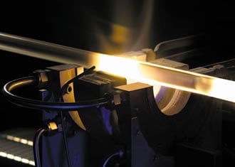
MCVD is a process that uses a hollow Silica (SiO2) Tube as a blank and fills the interior with a solid Silica and Germania (Ge02) mixture.
The hollow tube is constantly rotated at 100 RPM about its center axis. Silicon Tetraoxide, Germanium Tetraoxide and Oxygen (02) gasses are pumped into the blank. An external heat source, which varies with available technology, is applied to the tube and transverses from one end to the other. The system reaches temperatures of 1200oC and creates a reaction in the gasses. Si02 and Ge02 form as particles and fuse to the outer diameter of the tube while residual gasses pass through the opposite end of the tube. With the transversing heat source, the entirety of the tube is filled with solid particles until only a thin passage remains in the center of the Preform. The heat is increased by reducing the speed at which the heat source transverses the tube and the Preform is collapsed eliminating the passage-way.
The end product is the Preform that is used in the next step of the process.[6]
Overcladding
Overcladding is performed for one of two reasons.
- Overcladding will increase the diameter of the preform so that it reaches the specifications required for Fiber Drawing in the next step.
- Overcladding can create multiple cladding layers of varying refractive indices. This can be used to create a more beneficial refractive index profile to reduce attenuation in the Optical Fiber.
This process requires at least two hollow tubes made of cladding materials, one overclad tube must be bigger than the pre-existing preform core, the second overclad larger than the first overclad tube. The first overclad tube is positioned around the preform core rod and the second is positioned around the first overclad tube. A pressure gradient is produced where the pressure outside the second overclad tube is higher than the area inside the second overclad tube. This will cause the materials to fuse inwardly. A heat source provides heat to all three components causing the first overclad to collapse onto the preform core rod and the second overcald to collapse on the first overclad. This process produces a multiple overclad preform.[7]
Fiber Drawing[edit | edit source]
Furnace
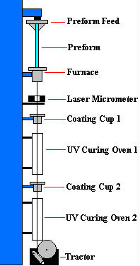
The furnace used in the drawing process has a longitudinal cavity in which the preform can be inserted vertically. The furnace is constructed of high temperature ceramics to allow high temperatures to be reached without causing changes in the furnace materials. An high frequency coil surrounds the vertical cavity and produces an electromagnetic field in order to heat the lower end portion of the preform and cause reflow in the material.[8]
Preform Heating
The preform is heated in the furnace to the point where it begins to flow. A portion of the preform is pulled from the bottom of the furnace and inserted into the roller mechanisms. The roller will pull the preform from the furnace at regulated speeds to produce fibers of adequate diameter.[9][10][11]
Response System[edit | edit source]
During the drawing process, dynamic measuring devices observe the diameter of the fiber being drawn at different areas of the process. These diameters are fed into a response system, which alters the speed of the rollers which pull on the fiber being formed from the heated preform material.
Laser measurement systems are commonly used because of their high accuracy and rapid response relay time.[12]
Variables and Benefits[edit | edit source]
Germania Content[edit | edit source]
The Germania content in a preform determines its refractive index. Using this, processors can alter the refractive properties of the core material and the cladding material.
Refractive Index Profile[edit | edit source]
The profile of the refractive index in optical fibers determine the quality of the optic fiber. Multimode optic are more affected by creating gradient indices, where as single modeW optic fibers are commonly left as step-index fibers since their diameter is minuscule. A gradient refractive index causes light to travel through the fiber as a sinusoidal wave and never reach a critical angle of reflection with the cladding. This increases the fibers resistance to attenuation with length of the fiber.
Graded-Index Plastic Optical Fiber Prepared by the Coextrusion Process[edit | edit source]
This process was created to produce graded-index fiber optics without the complications of forming parabolic refractive index during the preform stage.
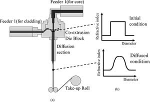
Apparatus[edit | edit source]
- Two Randcastle extrudersW with 12.7 mm diameters
- Single screw
- coextrusion die block
- diffusion section
- Doped material set in feeder 1 for core fabrication
- Pure material set in feeder 2 for cladding fabrication[13]
Process[edit | edit source]
The materials are heated to their subjective melting points and fed into the co-extrusion die block. The two materials form a core-cladding structure during extrusion. The material reaches the end of the diffusion sections and is drawn the same as conventional fiber drawing methods.[14]
Variances in Process[edit | edit source]
Viscosity Parameter
The refractive index profile in the co-extrusion process is controlled by the viscosity of the materials under high-temperature plasticizing.[15]
Diffusion
In the diffusion chamber of the process, a material is formed that has the doped material occupying the inner diameter and the outer radial layer being comprised of the pure undoped material. Under the heated conditions, diffusion occurs with the doped particles between the two concentrations of materials. Dopant diffuses outwards to the surface of the material. From simple diffusion laws, this action creates a parabolic refractive index profile in the radial direction of the material.[16]
References[edit | edit source]
- ↑ Williams, Eric, "Global Production Chains and Sustainbility: The case of high-purity silicon and its applications in IT and renewable energy", The United Nations University, Institute of Advanced Studies, 2000
- ↑ Philip St.J. Russell, "Photonic-Crystal Fibers", Journal of Lightwave Technology, Vol. 24, No. 12, December 2006
- ↑ Ramachandran (2001), "Higher-order-mode dispersion compensation: enabler for long distance WDM at 40 Gb/s", Proceedings of the SPIE 4532: 220–226, doi:10.1117/12.436014
- ↑ US Patent, 6334019, 2001, December, 25, Birks, Timothy A., "Single Mode optical Fiber"
- ↑ US Patent, 4033667, 1977, July, 5, Fleming, James W., "Multimoe Optical Fiber"
- ↑ US patent reference, 4217027, 1977, August, 29, MacChesney, Jon B., O'Connor, Paul B., "Optical fiber fabrication and resulting product"
- ↑ US patent reference, 6460378, 2000, February, 29, Xiaoyuan Dong, Siu-Ping Hong, Thomas John Miller, Don H Smith, "Collapsing a Multitube Assembly and Subsequent optical Fiber Drawing in the Same Furnace"
- ↑ US patent reference, 5410567, 1995, April, 25, Kevin R. Brundage, David J. Ulrich, "Optical Fiber Draw Furnace"
- ↑ US Patent, 4673427, 1987, June 16, Van Der Giessen, Aart A., Van Der Hulst, Victor A., Janssen Petrus J., "Method of and device for drawing an optical fiber from a solid"
- ↑ US patent reference, 4030901, 1977, June, 21, Kaiser, P., "Method for Drawing Fibers"
- ↑ US Patent reference, 4101300, 1978, July, 18, Imoto, K., "Method and apparatus for drawing optical fiber"
- ↑ Us Patent reference, 5443610, 1995, August, 22, Urruti, Eric H., "Apparatus for Controlling Fiber Diameter During Drawing"
- ↑ Hirose Ryoma, Asai Makoto, Konda Atsushi, Kioke Yasuhiro, "Graded-index plastic optical fiber prepared but the coextrustion process", Optical Society of America, 0003-6535/08/224177-09
- ↑ Hirose Ryoma, Asai Makoto, Konda Atsushi, Kioke Yasuhiro, "Graded-index plastic optical fiber prepared but the coextrustion process", Optical Society of America, 0003-6535/08/224177-09
- ↑ Hirose Ryoma, Asai Makoto, Konda Atsushi, Kioke Yasuhiro, "Graded-index plastic optical fiber prepared but the coextrustion process", Optical Society of America, 0003-6535/08/224177-09
- ↑ Hirose Ryoma, Asai Makoto, Konda Atsushi, Kioke Yasuhiro, "Graded-index plastic optical fiber prepared but the coextrustion process", Optical Society of America, 0003-6535/08/224177-09