
Molecular beam epitaxyW
is a method of thin film deposition that is useful for fabricating high performance photovoltaic devices.
Molecular beam epitaxyW
is a method of thin film deposition that is useful for fabricating high performance photovoltaic devices.
The original MBE at Michigan Tech was assembled in 1993 using ISA Riber, SVT Associates, Thermionics, k-Space, and Inficon components. It provided staff and students the ability to deposit thin high purity films under ultra high vacuumW(UHV) conditions. The system saw use up until April of 2001, at which point it was left under UHV and powered down. In late 2011, over a decade later, the chamber was found to be at atmospheric pressure and the process of reconditioning the system was initiated.
Silver(Ag), molybdenum(Mo), germanium(Ge), tin(Sn), iron(Fe), nickel(Ni), copper(Cu), silicon(Si) and carbon(C) sources were used prior to 2001. The silicon and carbon sources were changed from thermal to SVT Associates electron beam evaporating sources roughly two years after completion of the MBE.

The RIBER MBE 32 system is a highly flexible and efficient 3" single-wafer epi reactor, which provides all the necessary MBE tools and in-situ characterization capabilities to achieve state-of-the-art epitaxy of III-Vs, II-VIs, MCTs, nitrides and silicon alloys. The 8 cell ports are grouped together on the evaporation flange, which also includes cryoshrouds completely surrounding hot parts of the cells, ensuring maximum trapping of all residual species. The pump chamber also contains a cryoshroud to maximize gettering of low atomic weight gasses by the installed titanium sublimation pump system.
Two cryoshrouds are fixed to the inside of the source flange. One cryoshroud is a double-walled, lens-shaped assembly immediately adjacent the evaporation flange and serves to thermally isolate each of the sources while maximizing condensation of residual gasses. The second and main cryopshroud is supported by and connected to the evaporation flange. This cryoshroud has the same construction as the evaporation flange shroud. Each panel has a separate all metal liquid nitrogen inputs and outputs permitting independent or sequential cooling.
The evaporation flange can accommodate eight sources, four each with 2.75" and 4" flanges. It can be specifically adapted for the growth of mercury compounds or nitrides of group III elements. Gas-source MBE and CBE configurations combining the use of solid sources and/or gas sources are also available.

Michigan Tech's MBE system employs Model 16TTD manual shutters provided by ISA Riber and pneumatic rotary actuators(Bimba Pneu-Turn) are also available. The rotary actuators have been found, tested and deemed to be in working condition. A Humphrey Raceway solenoid valve consisting of nine (9) dual-use solenoids and a valve body capable of supplying nine actuators completes the automatic shutter system.
Introduction of samples is accomplished by use of a load lock chamber (R&D systems). This chamber can be vented (typically with UHP N2) and pumped independently of the evaporation chamber. In addition to the transfer arm sample holder, the chamber has attached to it two additional holders, one of which can be heated, for sample pre- and post-treatment. The sample transfer arm is manually operated, permitting limited rotation for alignment with the manipulator's sample holder.

The Ribar ARM3 manipulator provides rotation in two axes, one axis for placing the sample such that it faces towards or away from the sources and the other for rotation on an axis normal to the sample's face. It also permits heating of the sample to a maximum of 1000 degrees C. An Isa Riber MOB-300M molybdenum mounting block is specifically made for use with 3" diameter substrates but can accommodate mounting of smaller (2cm x 2cm) substrates with available carbon blanks.


A number of effusion cells are available for use; eight thermal and three e-gun cells. A plasma generator is also available. In situ analyzers consist of an Inficon Transpector residual gas analyzer, an Inficon SQC-310C deposition controller with two quartz crystal sensors and a reflection high energy electron diffraction (RHEED) system. One of the quartz crystal sensors is bellows-mounted and can be placed directly in the position occupied by the sample during film deposition, permitting very accurate deposition rate measurement.
Roughing is provided by a BOC Edwards QDP Drystar vacuum pump. Leybold Turbovac 1000C and Turbovac 361C turbomolecular pumps provide high vacuum pumping for the evaporation and load lock chambers, respectively. Ultra high vacuum conditions in the evaporation chamber are achieved with an ISA Riber PF-6 titanium sublimator and an ISA Riber PI-400-TTZ ion pump.
ISA RIBER PI-400-TTZ Ion Pump
ISA RIBER 401-1000 Ion Pump Power Supply
ISA RIBER PF-6 Titanium Sublimator
ISA RIBER Model 304-6 Titanium Sublimator Power Supply
Supplies power for Titanium filaments. 0 to 60 Amp selectable for 1 of 6 filaments and operates at 220V (50/60 Hz).
ISA RIBER Model JBA 12-1 Bayard-Alpert Ion Gauge
RIBER Model 307S2 Electrometer
ISA RIBER ABN 135L Effusion Cells
| CELL TYPE | SOLID SOURCE |
| MOUNTING FLANGE | CONFLAT 2-3/4" O.D. CF 35 |
| KNIFE EDGE TO LIP LENGTH | 283.5 mm |
| EXTERNAL SHIELD DIAMETER | 37.2 mm |
| BAKEOUT TEMPERATURE | 250°C |
| CAPACITY | 39 cc |
| CRUCIBLE INTERNAL LIP DIAMETER | 23.6 mm |
| CRUCIBLE INTERNAL LENGTH | 88.9 mm |
| CRUCIBLE MATERIAL | PBN (pyrolytic boron nitride) |
| TEMPERATURE RANGE | 0 - 1400°C |
| TEMPERATURE STABILITY | < 0.4°C |
| THERMOCOUPLE TYPE | WRe 5/26 |
| HEATING MODE | JOULE EFFECT / RADIATION |
| HEATING ASSEMBLY MATERIALS | Mo - Ta - PBN |
| FILAMENT TYPE | FLAT FOIL |
| MAXIMUM TEMPERATURE | 1500°C |
ISA RIBER TC 194 Temperature Control Units

TDK-Lambda EMS 30-33 1000W (1kW) AC to DC Power Supply

| AC Input | 1 kW models:
115 VAC (standard), 220 VAC (optional) single phase; All models 50/60 Hz |
| Rated Power (Watts) | 1000W (1kW) |
| Output Voltage (Volts) | 0 - 30V |
| Output Current (Amps) | 0 - 33A |
| Output Ripple (mV) p-p Carrier | 75mV |
| Output Characteristics | Regulation: 0.1%
Stability: 0.05% Transient response: 650 microseconds for 30% load change (models up to 20 VDC) Operating temperature: 0-50 Deg C full output, derate above 50 Deg C |
| Protective Features | Overvoltage (up to 300 VDC outputs)
Overtemperature Overcurrent |
| Programming | Front panel controls and remote analog resistance, voltage and current programming |
SVT Associates EBS-4 Electron Beam Evaporator
SVTA-EBS Compact evaporator is a very versatile source for depositing thin layers of Carbon, Silicon, Tantalum, Molybdenum, and most other refractory metals that are manufactured in wire form. Its exclusive design utilizes an electron beam power supply for electron emission and an integral flux monitor to regulate the deposition rate. The source material is typically a rod of 1-5 mm in diameter. When held at a positive potential, it attracts electrons emitting from the filament and is heated to an evaporation temperature to produce a flux of atoms. A linear motion feed through provides adjustment of the source position. Alternatively, materials in chunk or powder form may be evaporated from a special crucible. Typical applications include silicon MBE- metallization, magnetic thin films, doping, interface studies etc.
SVTA 3kW Power Supply
RHEED Image Analysis Hardware/Software package gives the user the necessary tools to gain insight into the thin film growth process and optimize material quality. The RHEED software is a multi-purpose program for analyzing RHEED patterns. The powerful software features tracking of RHEED intensity changes and measuring the rate of oscillations for quantitative determination of growth rate. It also has image analysis capabilities such as capturing and profiling. The software program takes input from a high sensitivity CCD digital camera. All components are outside the thin film deposition system hence retrofitting this package to existing machines is very simple.
Perkin-Elmer Model 06-190 10keV HEED Gun
Perkin-Elmer 20-330 RHEED Gun Control
K-Space (KSA) BP-M1 CCD Camera
KSA 300/400 Software
Transpector Ware V2.0 Software
VME 38 Roughing Pump Valve
Thermionics Northwest EM201.8-8-8B XYZ Manipulators
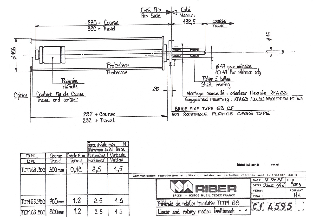
ISA RIBER TLTM 63/700 Linear and Rotary Motion Feedthrough
Diagram of TLTM 63/700 is available here: TLTM 63/700
ISA RIBER Model 304-4 Titanium Sublimator Power Supply


Electrometers display the current produced by the Bayard-Alpert (B-A) ionization gauges located in the main and load-lock chambers in meaningful units (torr). See this for a brief explanation of the theory of operation of B-A ionization gauges. The gauges installed in the MBE are the UHV nude type. The electrometers also serve as the control interface for the B-A ionization gauges. Overpressure protection is included, shutting off power to the B-A ionization gauge when the measured pressure exceeds approximately 10-3 torr. See this manual for operation of the electrometer.
Operating the Electrometers and B-A Ionization Gauges
DO NOT attempt to turn on the gauges when the pressure in the chamber is greater than 10-4 torr.
Degassing the B-A Ionization Gauge
If the chamber has become badly contaminated as a result of extended exposure to atmosphere or other event, or if the B-A gauges have been in continual operation for a very long period of time, the anode will likely need to be degassed. Press the DEGAS button on the electrometer to activate the degas circuit and leave in this mode for 10-15 minutes. While degassing, the reading on the electrometer will vary, potentially quite a lot, until condensed gas is driven from the anode.
The standard operating procedure for the MBE system is described below in details. The steps should be followed exactly during every sequence.
Note: Bullet points should be followed sequentially, as sub-steps.


Note: Make sure that the ion pumps, the TMP pumps, and the ion gauge in the main chamber are not increasing. This will indicate a leak. Close the valve if the TMP loads increase, or if there is a large fluctuation in the main chamber ion gauge reading, or ion pump readings, close the vent valve.
WARNING: Do not latch the exchange window until the N2 vent line is closed. The internal pressure buildup can severely damage the system.
Note: This procedure assumes that substrates are being loaded into the load-lock chamber, for transfer. If the load-lock is in a vented state (correct system section isolation is set out in "Venting the Load-Lock"), and no substrate loading is necessary, proceed from step 8 on.
Note: Move the transfer arm away from the sample holder before changing the angle, so that they do not collide.
Note: Before disengaging the transfer arm, release the rubber belt connecting the rotator motor to the external substrate rotator, to relieve tension built up in the transfer.
The plasmatron is used to energize either ultra-high purity (UHP) gases of N2, O2, or Ar for the growth of semiconductors. This procedure details the use of N2 but is not exclusive to N2; it is detailed because of the Mosaic project involves the growth of nitrides.
Note: You might have to go to higher power or throttle the gate valve on the main chamber TMP to allow for high pressures.
Plasmatron Wattages for Certain Pressures
| Pressure (Pa) | Power (W) |
| 2 | 414 |
| 2.5 | 337 |
| 3 | 326 |
| 4 | 327 |
| 5 | 332 (stabilizes at 275 after 30 mins) |
| 6 | 350 |
| 7 | 363 |
| 8 | 380 |
For sample cleaning, follow the instructions next to the fume hood.
If required, more de-ionized water can be obtained in Room 414. Run the faucet for a few minutes to clear the line before filling the bottle
Large bottles of solvents are stored in the cabinet below the fume hood. These are used to refill the smaller bottles used in the cleaning process.
Silicon substrates are located in the bottom drawer of the tall, tan cabinet next to the fume hood. Aluminium nitride substrates are located in the grey substrate box atop this cabinet.
This process assumes that the sample is already in the MBE main chamber and the sample is at 135o.
Italicized text indicates inconstant temperatures, rates, and deposition durations.
Note: Watch the effusion cell voltage supply during the growth. If the "overvoltage" light turns on, turn the respective voltage supply off, then back on. Otherwise, the temperature will plummet, to the possible damage of the crucible in the given effusion cell.
If the main chamber of the MBE is open to atmosphere to replace the QCM crystal, replace or refill the effusion cells, modify the plasmatron, or any other maintenance, the system will need to be baked to drive off water vapor.
After a bake out the system will be in an idle state where the cryo shrouds are empty of water and only the ion pumps will be running. The cryo bypass is removed to let out steam during the bake out. The pressure of the Load-Lock (4.1×10⁻⁷ torr) and the Main Chamber (4.8×10⁻¹⁰ torr) will be monitored by ion gauges. All the effusion sources will normally be cold.
Roughing is provided by a BOC Edwards QDP Drystar vacuum pump. The foreline has three connection points, backing for each of the turbomolecular pumps and roughing at the load-lock chamber. All connection points are individually valved with manually operated Isa Riber isolation valves.
The roughing pump operates continuously while the system is under vacuum.
ISA RIBER JTC 6 T Thermocouple Gauge
ISA RIBER JTC 6 C Power Supply
ISA Riber Company - Riber's Website
SVT Associates, Inc. - SVT's Website
k-Space Associates, Inc. - KSA's Website
TLI Enterprises, Inc. "Thermionics" - Thermionic's Website
Inficon - Inficon's Website
The Processed Water System is checked to ensure it is up to (5) occasions daily at the Dow building. The system is also monitored by the CHP 24/7. When the supply temperature gets to 68F or above, the CHP operator will receive an alarm status and phone calls are made. If it is desired to be notified at this point please contact the heating plant at 487-2707 or chp@mtu.edu declaring so.
Many times Mike or Thomas Polkinghorn will catch the system misbehaving when they are at work before the CHP does. Please do not hesitate to call Thomas Polkinghornat 370-1629 weekdays through 3:30PM to report troubles. After 3:30PM the CHP should be notified.
Lastly, this system needs to be filled slowly into your equipment initially. A sudden loss of pressure on the system can keep the pumps from completing this rather long loop. Please keep this in mind when hooking up equipment as filling to quick can jeopardize the system for all that use it. If large amounts are to be drawn the system should be monitored while doing so.
| License | CC-BY-SA-3.0 |
|---|---|
| Cite as | Pasionek, Caekstru, Jrozario, Gcanzalo (2011–2025). "MBE protocol:MOST". Appropedia. Retrieved October 4, 2026. |