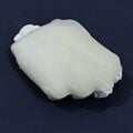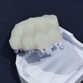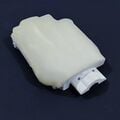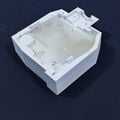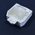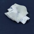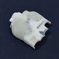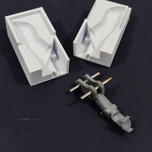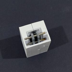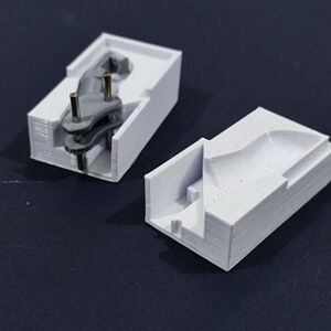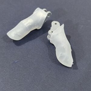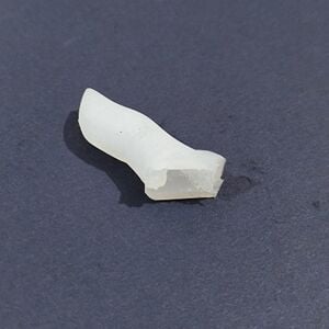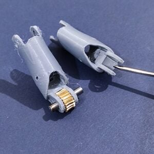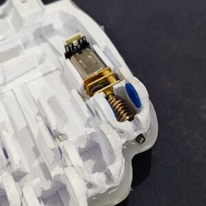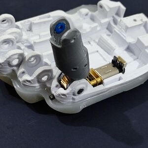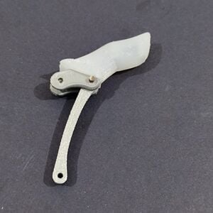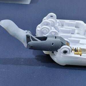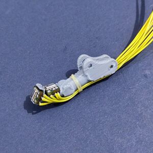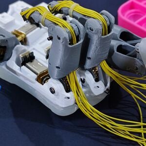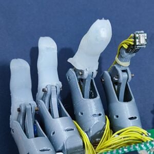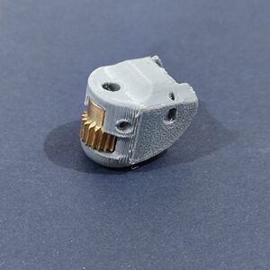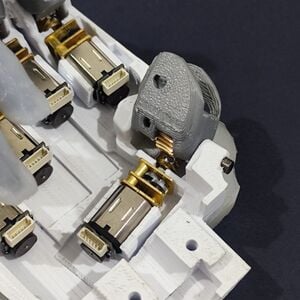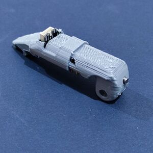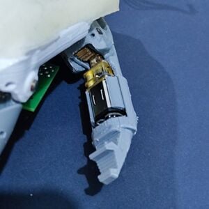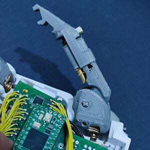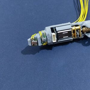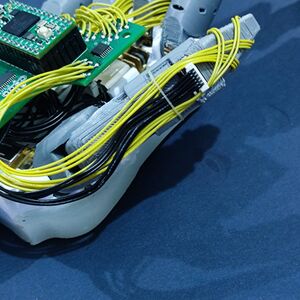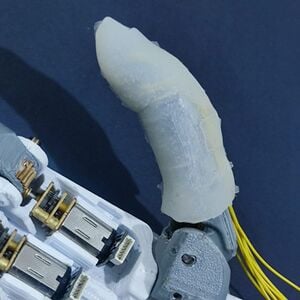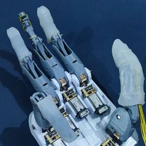
WeArm is an open source low-cost, low-complexity prosthetic device with human-like range of motion and touch feedback.
Disclaimer[edit | edit source]
Information contained in this documentation is limited to material and building instructions needed to start testing.
Testing the WeArm has not been completed due to a problem in I2C communication and needs more work and inputs. The I2C communication between I2C Master (Hand Teensy 4.0) and I2C Slaves (PCA9685, TCA9534, MPL115A, Socket Teensy 4.0) has shown instability.
Attribution[edit | edit source]
This project is built on the work of Okezue Bell, the creator of WeArm prosthetic. All information including contact details, license terms, original build manual, and other work can be found in WeArm Open Source Build Manual
This page is descripting building a right-hand prosthetic. If you are interested to build a left-hand device, please refer to the original work in WeArm Open Source Build Manual.
Downloadable files are provided by, or built on the files provided by Okezue Bell in WeArm Open-Source Build | Code, Diagram, & Print Files
Things to buy[edit | edit source]
Material List[edit | edit source]
Table below is sorted by supplier. In some places, most of listed material could be found in local market. In addition to the list below, you will need 12 VDC power supply, 7.4 V battery with charger if you plan to use batteries, workshop tools like Dremel and soldering station.
| Item | Unit | Quantity | Supplier | Link |
|---|---|---|---|---|
| Dragon Skin 00-20 molding silicone | 2.45 pounds | 1 | Amazon | link |
| ECOFLEX 00-35 molding silicone | 2 lbs | 1 | Amazon | link |
| PLA+ filament | 1kg spool | 1 | Amazon | link |
| TPU filament | 1kg spool | 1 | Amazon | link |
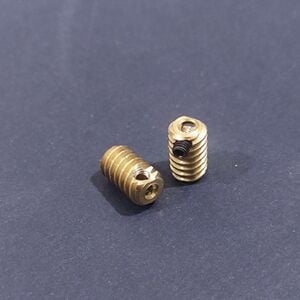
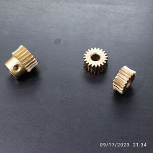
| Worm gear set, module 0.5, ratio 1:10 | pcs. | 6 | Amazon | link |
| Electrode pads | 48 pcs pack | 1 | Amazon | link |
| 2mm x 200 mm solid round rod | 2 pcs pack | 1 | Amazon | link |
| 3mm x 200 mm solid round rod | 2 pcs pack | 1 | Amazon | link |
| 4mm x 200 mm solid round rod | 2 pcs pack | 1 | Amazon | link |
| Magnetic encoder | pair kit | 3 | Pololu | link |
| 6-Pin JST SH-style connector | pcs | 6 | Pololu | link |
| 210:1 micro metal gearmotor | pcs | 6 | Pololu | link |
| 3.3V, 1A step-down voltage regulator | pcs | 1 | Pololu | link |
| 5V, 5.5A step-down voltage regulator | pcs | 1 | Pololu | link |
| 0.01uF 0603 capacitor | pcs | 3 | DigiKey | link |
| 0.1uF 0603 capacitor | pcs | 6 | DigiKey | link |
| 0.4Ω 1206 resistor | pcs | 6 | DigiKey | link |
| 1.5nF 0603 capacitor | pcs | 1 | DigiKey | link |
| 10kΩ 0603 resistor | pcs | 5 | DigiKey | link |
| 10uf 0603 capacitor | pcs | 4 | DigiKey | link |
| 1kΩ 0603 resistor | pcs | 2 | DigiKey | link |
| 1MΩ 0603 resistor | pcs | 1 | DigiKey | link |
| 1nF 0603 capacitor | pcs | 1 | DigiKey | link |
| 1uF 0603 capacitor | pcs | 25 | DigiKey | link |
| 2.2uF 0603 capacitor | pcs | 3 | DigiKey | link |
| 220Ω 0402 resistors | pcs | 12 | DigiKey | link |
| 22uF 0603 capacitor | pcs | 1 | DigiKey | link |
| ADS1298 | pcs | 1 | DigiKey | link |
| L7805CV | pcs | 1 | DigiKey | link |
| TPS60403DBVRG4 | pcs | 1 | DigiKey | link |
| TPS73225DBVT | pcs | 1 | DigiKey | link |
| DRV8833 | pcs | 3 | DigiKey | link |
| PCA9685 | pcs | 1 | DigiKey | link |
| TCA9534 | pcs | 1 | DigiKey | link |
| MPL115A temp/pressure module | pcs | 6 | DigiKey | link |
| TEENSY 3.2 | pcs | 2 | DigiKey | link |
| Palm 4-layer PCB | pcs | 1 | PCBWay | link |
| Socket 2-layer PCB | pcs | 1 | PCBWay | link |
| Sensor 2-layer PCB | pcs | 6 | PCBWay | link |
Printed Circuit Boards (PCBs)[edit | edit source]
There are 3 PCBs in the WeArm project. To order a PCB (unpopulated), you will need the associated Gerber file for each board, which can be generated using the Eagle software. All Gerber files are uploaded and ready for use. To learn about generating Gerber files in Eagle, refer to this link.
| Item | Type | Pcs. | Eagle File | Gerber File | Image |
|---|---|---|---|---|---|
| Main microcontroller palm PCB | 4-layer | 1 | File:MC-Eagle.zip | File:MC 2023-08-07.zip | 
|
| EMG socket PCB | 2-layer | 1 | File:EMG-Eagle.zip | File:EMG 2023-07-16.zip | 
|
| Pressure sensor PCB | 2-layer | 6 | File:Haptic-Eagle.zip | File:Haptic-F 2023-07-16.zip | 
|
Preparations[edit | edit source]
STL 3D Printing Files[edit | edit source]
| Part | Quantity | Material | STL | Image |
|---|---|---|---|---|
| Back palm | 1 | PLA+ | b-palm | 
|
| Front palm | 1 | PLA+ | f-palm | 
|
| Back palm mold | 1 | PLA+ | b-palm-mold | 
|
| Front palm mold | 1 | PLA+ | f-palm-mold | 
|
| Thumb holder | 1 | PLA+ | thumb-holder | 
|
| Thumb unit | 1 | PLA+ | thumb-single-unit | 
|
| Thumb skin | 1 | PLA+ | thumb-skin | 
|
| Thumb skin mold right | 1 | PLA+ | mold-thumb-skin-r | 
|
| Thumb skin mold left | 1 | PLA+ | mold-thumb-skin-l | 
|
| Finger proximal unit | 4 | PLA+ | r-proximal | 
|
| Finger distal unit | 4 | PLA+ | sm-distal | 
|
| Distal unit skin | 1 | PLA+ | sm-distal-skin | 
|
| Finger mold right | 1 | PLA+ | mold-distal-r | 
|
| Finger mold left | 1 | PLA+ | mold-distal-l | 
|
| Wrist holder front | 1 | PLA+ | p-f-wrist-s | 
|
| Wrist holder back | 1 | PLA+ | p-b-wrist-s | 
|
| Wrist damper | 1 | TPU | damper | 
|
| Link | 4 | PLA+ | link | 
|
| Sleeve | 8 | TPU | sm-ring-sleeve | 
|
| Bearing | 6 | TPU | sm-bearing | 
|
Steel Rods[edit | edit source]
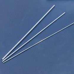
Rods of different diameters (2mm, 3mm, 4mm) are used to connect WeArm components and ensure relative movement between them. Use Dremel tool to cut the rods to size, grind the D-shaped axis, and grind cut edges as well.
| Diameter | Cut length | Quantity | Where used | Image |
|---|---|---|---|---|
| 2 mm | 9 mm | 4 | Link with back palm | 
|
| 2 mm | 11 mm | 4 | Link with finger distal unit | 
|
| 2 mm | 14.5 mm | 4 | Finger distal unit with finger proximal unit | 
|
| 2 mm | 22 mm | 2 | Hold distal unit in place when silicone molding | 
|
| 3 mm | 9.3 mm | 1 | Worm gear shafts - thumb motor adduction/abduction | 
|
| 3 mm | 9.3 mm | 1 | Worm gear shafts - thumb motor flexion/extension | 
|
| 3 mm | 14 mm | 4 | Worm gear shafts - finger motors | 
|
| 4 mm | 19.5 mm | 4 | Wheel gear axes - fingers | 
|
| 4 mm | 18.8 mm | 1 | Wheel gear D-shaped axis - thumb adduction/abduction | 
|
| 4 mm | 34 mm | 1 | Wheel gear axis - thumb flexion/extension | 
|
Worm Gear/Wheel Gear[edit | edit source]
Palms Silicone Molding[edit | edit source]
ECOFLEX 00-35 is used to create the soft coating for back and front palm. Before working with ECOFLEX 00-35 silicone, make sure to read the instruction and take care of pot life and curing time.
Fingers Silicone Coating[edit | edit source]
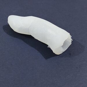
Dragon Skin 00-20 is used to create silicone coating for all fingers (little, ring, middle, index, and thumb). The steps to make the silicone coating for little and ring fingers and the steps to make the silicone coating for middle, index, and thumb fingers are not the same. Middle, index and thumb fingers have touch sensors below the silicone coating (2 sensors for each finger). Before working with Dragon Skin 00-20 silicone, make sure to read the instruction and take care of pot life and curing time.
Little & Ring[edit | edit source]
Middle & Index[edit | edit source]
Thumb[edit | edit source]
Assemblies[edit | edit source]
Electronics and PCB Soldring[edit | edit source]
For completing the PCBs, you will a work station including an iron gun and heat gun. Always use solder paste for SMD components.
Teensy 4.0[edit | edit source]
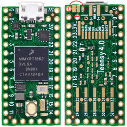
In this project, the Teensy will be supplied using an external power supply (12 VDC or 7.4 VDC batteries). By default, the Vin in Teensy board is connected to VUSB by a small bridge in the back side. This bridge should be cut before connection to an external power supply.
Power Supplies[edit | edit source]
Supply 12VDC (or 7.4VDC battery) to the 5VDC and 3.3VDC step-down convertors. Note the power supply, convertors, and PCBs have a shared ground.
Main MicroController Board (MC)[edit | edit source]
All touch sensors, motor encoders, and I2C communication wires to the EMG baord should be soldered or connected to the MC board. The board is powered using 5VDC, 3.3VDC, and GND.
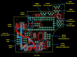
After adding a new component that is a part of the I2C network (PCA9685, TCA9534, MPL115A, EMG socket PCB), upload the I2C scanner from Wire library and run the scan to make sure that the recently added part is detected correctly. Refer to Software section for the libraries to be used.
EMG (Socket) Board[edit | edit source]
The board is powered using 5VDC and GND. Note that when using the step-down convertors, the LM7805 voltage regulator is not needed.
For I2C, connect SLA (Teensy: pin18) and SCL (Teensy: pin19) from EMG board to SLA and SCL wirepads in MC board.
For the electrodes, connect ground electrode (elbow) to GNDEL wirepad, and connect 3 electrodes (2 on arm, 1 on biceps) to any 3 positive inputs of ADS1298 in EMG board.
Touch Sensor[edit | edit source]
For each touch sensor, you will need 5 wires, 10 cm each. Make sure to use small gauge wires (AWG22 or AWG24). After completing soldering the PCB and wiring, it is recommended to test each sensor using Arduino UNO board. Use the built-in example "getpressure" in Adafruit_MPL115A2 library. If everything is OK, you should get reading of temperature and pressure, depending on your location.
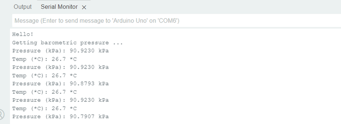
Each touch sensor should be wired to the MC board. The table below shows the mapping between touch sensor wires and MC wirepads. This should be repeated for all touch sensors.
| Touch Sensor PCB | Main MC PCB |
|---|---|
| SDA | SDA |
| GND | GND |
| PE4 | RST |
| +3V3 | VDD |
| SCL | SCL |
Magnetic Encoders[edit | edit source]
Before starting fingers assembly, solder the magnetic encoders to the micro motors and insert a magnetic disc to the back shaft of each motor. Insert a worm gear into each motor front shaft, and fasten the socket screw.
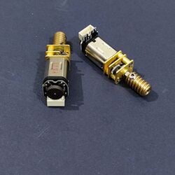
Each motor encoder should be wired to the MC board. The table below shows the mapping between motor encoders wires and MC wirepads. This should be repeated for all encodres.
| Motor Encoder | Mian MC PCB |
|---|---|
| GND | GND |
| OUT A | MEn1 |
| OUT B | MEn2 |
| VCC | +3V3 |
| M1 | MPn1 |
| M2 | MPn2 |
Little, Ring, Middle, Index[edit | edit source]
Thumb[edit | edit source]
Software[edit | edit source]
Files Download[edit | edit source]
Arduino Setup[edit | edit source]
To enable Teensy 4.0 programming, Teensyduino should be installed on Arduino. For more information, refer to Download Teensyduino. Please note tha this project is completed using Arduion IDE version 2.1.1
Also, the Adafruit PWM Servo Driver Library Adafruit_PWMServoDriver.h (and its dependencies) should be installed using the Arduion library manager.
Some of the default libraries in Teensyduino should be replaced with updated ones (Wire.h, SPI.h). To complete this,
1. Open the hand-control code, and in hand-control. tap, pause the mouse over the Wire.h library. Location folder will be displayed.

2. Copy the location folder and open "libraries" folder.
3. Replace both Wire and SPI folders with the ones downloaded from this page.
