I carried out this project during one of my semesters where I designed a solar water heating system using Parabolic Trough Collector and Fresnel Collector for a textile industry in Pakistan. Moreover, a comparative analysis of both types of collectors was also performed. The Project detailed theoretical understanding of solar water heaters as well as numerical calculations related to solar irradiance, solar beam direction, sun tracking strategies, heat transfer, thermal collector efficiency etc. Prior knowledge of solar analysis will indeed be an excellent help when carrying out research on Agrivoltaics. Hence, this project has equipped me with the basic tools related to solar energy which will be beneficial to carry out future work in the domain of Agrivoltaics.
The text below entails a detailed outlook on solar collector and its types as well as solar analysis (including calculations) for the project. A brief overview of thermal analysis and design and performance etc. for solar thermal collectors is also mentioned. Finally, a comparison of both types of technologies is included as well.
Abstract[edit | edit source]
My project is a way forward towards eradication of already existing energy crisis in Pakistan. Pakistan being an underdeveloped country is focused on improving its economic condition, with the energy crisis especially the electric and petroleum gas, being a significant barrier in its way. Of the total industrial power consumption in the country, about 40% of the power requirement is credited to the textile sector which chiefly uses it for steam generation. The project here outlines the application of the solar thermal energy for steam generation required for textile sector in the country. It is only that the initial investment of the solar projects is high but these projects are a green solution and a lifetime investment especially in a geographical location like Pakistan, which lies in a high solar insolation zone, and where the payback period also gets reduced. Pakistan lies in between 24˚-37˚ latitude which is one of the most favorable regions for solar thermal energy utilization. The project is focused to design Parabolic Trough Concentrators, Heat Exchangers and then other auxiliaries required for the conversion of solar radiations into useful heat gain which in turn generates steam, required for different processes in the textile industry. With thermal and solar modelling of Parabolic Trough Collectors and Heat Exchangers being the major contributors to the study, a detailed land analysis is also conducted. The study tends to optimize and thus provide the best possible outcome with least energy losses, reduced investment recovery period and the most environment friendly solution to the prevailing energy shortages in the country.
Introduction[edit | edit source]
The purpose of my project is to generate steam by solar radiation. This can be achieved by different solar collectors depending on the required temperature range. For low range temperature about 80⁰C flat plate collectors are used. For high temperature range up to 400 ⁰C Parabolic Trough Collectors are used and for higher temperature range greater than 1500 ⁰C Parabolic Dish collectors are used. I have selected a local industry for the case study of designing suitable solar thermal collectors. The energy demand for this industry is 20 MW for steam generation of 22 tons/hour at a pressure of 8 bar. For this case, I have designed Parabolic Trough collector and Fresnel collector and also checked their feasibility.
The calculations are done according to the following steps:
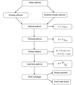
Solar Collector[edit | edit source]
A device used to collect, absorb, and transfer solar energy to a working fluid, such as water or air. Solar heat can be used for heating water to back up heating system. The heart of a solar collector is its absorber. The carrier fluid for heat transfer flows through a heat carrying pipe, which is connected to the absorber strip. In flat absorbers, two sheets are sandwiched together allowing the medium to flow between the two sheets.
Types of Collector[edit | edit source]
- Stationary Collector
- Sun tracking
Stationary Collector (Flat Plate Collector)[edit | edit source]
Flat plate collectors are used for air and water heating. These are normally used in residential buildings to heat water for bathing, washing and heating outdoor swimming pools and hot tubs.
Concentrating Collector[edit | edit source]
In quest of increased delivery temperature than those possible with flat plate collector, an optical device between sun and collector is interposed. The concentrating collectors concentrate all the solar insulation onto a receiver through which the heat transfer fluid when passed absorbs this energy. The high efficiency of this collector is due to small heat loss area.
Solar Parabolic Trough Concentrator Technology[edit | edit source]
Parabolic trough concentrator (PTC) systems are currently the most mature and cost-effective technology to generate electricity. In a PTC, an array of parabolic-shaped mirrors concentrates the incident solar radiation onto the focal line where a tubular receiver is placed. The receiver generally consists of an absorber tube and a protective glass envelope surrounding the absorber. The absorbed solar radiation is transferred to a heat transfer fluid (HTF) that flows through the absorber tube and provides the thermal energy for the power cycle. The HTF is also used to provide heat to the thermal storage system, either directly using the fluid, or indirectly by transferring heat to a storage medium.
Linear Fresnel Collectors[edit | edit source]
A concentrating linear Fresnel reflector – is a specific type of linear Fresnel reflector (LFR) technology. Linear Fresnel reflectors use long, thin segments of mirrors to focus sunlight onto a fixed absorber located at a common focal point of the reflectors.
Parabolic Dish Reflector[edit | edit source]
The parabolic dish reflector uses two axis tracking mechanism. Dish structure fully tracks the sun to reflect the beam onto thermal receiver. Temperatures greater than 1500ᵒC and concentration ratios between 600ᵒC - 2000ᵒC are achievable with these dish reflectors.
Heliostat Field Collectors:[edit | edit source]
The heliostats are mirrors with solar tracking on two axes and capable of concentrating the reflected solar radiation on a focal point located at the top of a tower in which the receiver element is placed. The basic difference between the central receiver concept of collecting solar energy and the trough or dish collectors is that in this case, all of the solar energy to be collected in the entire field is transmitted optically to a small central collection region rather than being piped around a field as hot fluid.
The Solar Analysis[edit | edit source]
The Sun[edit | edit source]
The sun is a sphere of intensely hot gaseous matter with a diameter of 1.39x10⁹ m and is, on the average 1.5x10¹¹ m from the earth. As seen from the earth, the sun rotates on its axis about once every 4 weeks.
The sun has an effective blackbody temperature of 5777 K. The temperature in the central interior regions is variously estimated at 8*106 to 40*106 K and the density is estimated to be about 100 times that of water. The sun produces its energy in its core by the fusion of hydrogen into helium etc. and emits a wide range of radiation.
The Solar Constant[edit | edit source]
The solar constant GSC is the energy from the sun per unit time received on a unit area of surface perpendicular to the direction of propagation of the radiation at mean earth-sun distance outside the atmosphere. The World Radiation Center has adopted a value of 1367 W/m2, with an uncertainty of the order of 1%.
Spectral Distribution of Extraterrestrial Radiation[edit | edit source]
In addition to the total energy in the solar spectrum (i.e. the solar constant), it is useful to know the spectral distribution of the extraterrestrial radiation, that is the radiation that would be received in the absence of the atmosphere.
Variation of Extraterrestrial Radiation[edit | edit source]
Two sources of variation in extraterrestrial radiation must be considered. The first is the variation in the radiation emitted by the sun. There are conflicting reports in the literature on periodic variations of intrinsic solar radiation. It has been suggested that there are small variations(less than ± 1.5%) with different periodicities and variation related to sunspot activities.
The extraterrestrial radiation incident on the plane normal to the radiation on the nth day of the year is given by:
𝐺𝑜𝑛 = 𝐺𝑠𝑐(1 + 0.033𝑐𝑜𝑠(360𝑛/365))
Variation of the earth-sun distance however, does lead to variation of extraterrestrial radiation flux in the range of±3.3% .
Definitions[edit | edit source]
Air Mass (M)[edit | edit source]
The ratio of the mass of atmosphere through which beam radiation passes to the mass it would pass through if the sun were at the zenith. Thus at sea level m=1 when the sun is at the zenith and m=2 for a zenith angle of 60°.
𝑚 =1/𝑐𝑜𝑠𝚹
Beam Radiation[edit | edit source]
The solar radiation received from the sun without having been scattered by the atmosphere. Beam radiation is often referred to as direct solar radiation.
Diffuse Radiation[edit | edit source]
The solar radiation received from the sun after its direction has been changed by scattering by the atmosphere. Diffuse radiation is referred as sky radiation.
Total Solar Radiation[edit | edit source]
The sum of the beam and the diffuse solar radiation on a surface. They are also referred to as global radiation.
Irradiance[edit | edit source]
The rate at which radiant energy is incident on a surface per unit area of surface. The symbol G is used for solar irradiance. Its unit is W/m2.
Irradiation[edit | edit source]
The incident energy per unit area on a surface, found by integration of irradiance over a specified time, usually an hour or a day .Insolation is a term applying specifically to solar energy irradiation. The symbol H is used for insolation for a day and the symbol I is used for insolation for an hour.
Emissive Power[edit | edit source]
The rate at which radiant energy leaves a surface per unit area by emission only. Its unit is W/m2
Radiosity[edit | edit source]
The rate at which radiant energy leaves the surface per unit area by combined emission, reflection and transmission.
Solar Time[edit | edit source]
Time based on the apparent angular motion of the sun across the sky, with solar noon the time the sun crosses meridian of the observer. Solar time is the time used in all of the sun-angle relationship it does not coincide with local clock time. It is necessary to convert standard time to solar time by applying two corrections. First there is a constant correction for the difference in longitude between the observer’s meridian (longitude) and the meridian on which the local standard time is based. The sun takes 4 min to transverse 1° of longitude. The second correction is from the equation of time, which takes into account the perturbations in the earth’s rate of rotation which affect the time the sun crosses the observer’s meridian. The difference in minutes between solar time and standard time is:
𝑆𝑜𝑙𝑎𝑟 𝑡𝑖𝑚𝑒 − 𝑠𝑡𝑎𝑛𝑑𝑎𝑟𝑑 𝑡𝑖𝑚𝑒 = 4(𝐿𝑠𝑡 − 𝐿𝑙𝑜𝑐) + 𝐸
Where 𝐿𝑠𝑡 is the standard meridian for the local time zone and 𝐿𝑙𝑜𝑐 is the longitude of the location in question and E is the equation of time.
𝐸 = 229.2(0.000075 + 0.001868𝑐𝑜𝑠𝛽 − 0.032077𝑠𝑖𝑛𝛽 − 0.014615𝑐𝑜𝑠2𝛽 − 0.04089𝑠𝑖𝑛2𝛽)
Direction of Beam Radiation[edit | edit source]
The geometric relationship between a plane of any particular orientation relative to the earth at any time (whether that plane is fixed or moving relative to the earth) and the incoming beam solar radiation, that is, the position of the sun relative to that plane, can be described in terms of several angles.
Latitude Angle (Φ)[edit | edit source]
The angular location north or south of the equator, north positive;-90° ≤ φ ≤ 90°.
Declination Angle (δ)[edit | edit source]
Angle between sun ray and equatorial plane is called declination angle (δ).The time of the year is specified by declination angle. Variation in declination angle throughout the year is given by the equation
𝛿 = 23.45𝑠𝑖𝑛 [360°((284 + 𝑛)/365)]
Where n=day of the year
Slope (β)[edit | edit source]
The angle between the plane of the surface in question and the horizontal; 0° ≤ β ≤ 180°
Surface Azimuth Angle (γ)[edit | edit source]
The deviation of the projection on a horizontal plane of the normal to the surface from the local meridian, with zero due south, east negative and west positive; -180° ≤ γ ≤ 180°.
Hour Angle (ω)[edit | edit source]
Solar hour angle directly related to sun’s position in the sky. The unit of angular measurement of time is hour angle. Time of the day is specified by hour angle. The hour angle is zero at local solar noon, and increases by15° for every hour before local solar noon and decrease by 15° for each hour after solar noon.
Solar Altitude (αs)[edit | edit source]
Solar altitude is the angle between sun beam and its horizontal projection. Solar altitude angle is angular distance of the sun from the horizontal. Solar altitude angle is zero at sunrise and sunset and maximum at solar noon. This angle changes throughout the day. It also varies with season.
𝑠𝑖𝑛𝛼𝑠 = 𝑠𝑖𝑛𝜑𝑠𝑖𝑛𝛿 + 𝑐𝑜𝑠𝜑𝑐𝑜𝑠𝛿𝑐𝑜𝑠𝜔
Solar Azimuth (γs)[edit | edit source]
Solar azimuth is the angle between projection of sun-earth line and local meridian pointing to equator. Obviously is the case of northern hemisphere it will point due south and in case of southern hemisphere it will be due north.
𝑠𝑖𝑛𝛾𝑠 = cos 𝛿𝑠𝑖𝑛𝜔/𝑐𝑜𝑠𝛼
Solar Zenith Angle (𝚹𝐳)[edit | edit source]
Angle between a solar ray and local vertical direction. It is the complement of solar altitude angle.
𝛼𝑠 + 𝚹𝑧 = 90°
Angle of Incidence (Ѳ)[edit | edit source]
The angle between the beam radiation on a surface and the normal to that surface.
Sun Tracking Strategies[edit | edit source]
Line focus concentrators are rotated about a single axes so as to minimize the angle of incidence. Some most popular orientation of concentrator axes are:
Horizontal East West Axes[edit | edit source]
For a plane rotated about a horizontal east west axes with continuous adjustments to minimize the angle of incidence.
𝐶𝑜𝑠𝜃 = (1 − 𝑐𝑜𝑠2𝛿𝑠𝑖𝑛2𝜔)1/2
And the angle ρ the collector makes with the south axis.
𝑡𝑎𝑛𝜌 = 𝑡𝑎𝑛𝛼/𝑐𝑜𝑠𝛾𝑠
Horizontal North-South Axis[edit | edit source]
For a plane rotated about a horizontal north south axis with continuous adjustments to minimize the angle of incidence. 𝑐𝑜𝑠𝜃 = [(𝑠𝑖𝑛∅𝑠𝑖𝑛𝛿 + 𝑐𝑜𝑠∅𝑐𝑜𝑠𝛿𝑐𝑜𝑠𝜔)2 + 𝑐𝑜𝑠2𝛿𝑠𝑖𝑛2𝜔]1/2
And the angle the collector makes with east axis in the morning and west axis in the afternoon.
tan 𝜌 = tan 𝛼/𝑠𝑖𝑛𝛾𝑠
Comparison Between Different Tracking Strategies[edit | edit source]
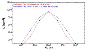
Figure2.1 shows the comparison of different sun tracking strategies throughout the day on 22nd June. As can be seen from the plot, by the north-west axis tracking more energy can be extracted than by using the other tracking strategy
Calculations for IB[edit | edit source]
The detailed calculations for extra-terrestrial radiations reaching the ground for the mid-day of the month of January i.e. 17th January at noon for Karachi are performed. The latitude for Karachi is 𝜙 = 24.86
For 17th January at noon where n=17: The declination angle is given by:
𝛿 = 23.45. sin [(284 + 𝑛).360/365]
𝛿 = −20.92
The sunset hour angle is calculated using:
𝜔𝑠𝑠 = 𝑐𝑜𝑠−1(− tan(𝜙) . tan(𝛿))
𝜔𝑠𝑠 = 79.78
The day length for 17th January is:
𝑇𝑑 = 2. 𝜔𝑠𝑠/15
𝑇𝑑 = 10.63
𝑇𝑛 = 𝑇𝑑 /2
𝑇𝑛 = 5.31
𝑇𝑠𝑠 = 12 + 𝑇𝑛
𝑇𝑠𝑠 = 12 + 5.31
𝑇𝑠𝑠 = 5: 19: 08 𝑃𝑀
𝑇𝑠𝑟 = 12 − 𝑇𝑛
𝑇𝑠𝑟 = 6: 40: 52 𝐴𝑀
At noon,
𝜔 = 0
Using the North South tracking strategy the incidence angle of the radiations is:
𝑐𝑜𝑠𝜃 = (((sin(𝜙) sin(𝛿) + cos(𝜙) cos(𝛿) cos(𝜔))2 + 𝑐𝑜𝑠2(𝛿)𝑠𝑖𝑛2(𝜔))1⁄2)
𝜃 = 45.786
The monthly average solar radiations are found using:
𝐻0 = 24 × 3600 × 1367/ 𝜋 (1 + 0.033 cos(360n/365)[cos(𝜙) cos(𝛿) sin(𝜔𝑠𝑠) + (𝜋. 𝜔𝑠𝑠 /180) sin(𝜙) sin(𝛿)]
𝐻0 = 24238112.34
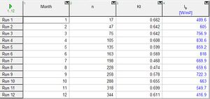
The clearness index values for different months of year are taken from Ahmad (1) and for the month of January:
𝐾𝑡 = 0.662
Now,
𝐻̅ = 𝐻0 × 𝐾𝑡
To convert the monthly extra-terrestrial radiation energy to the power generated we use the following algorithm:
𝐼 = 𝑟𝑖. 𝐻̅ / 3600
𝑎 = 0.409 + (0.5016 ∗ (sin(𝜔𝑠 − 60))
𝑎 = 0.578
𝑏 = 0.6609 − (0.4767 ∗ (sin(79.78 − 60))
𝑏 = 0.499
𝑟𝑖 = (𝜋 /24)(𝑎 + 𝑏 cos 𝜔) [(cos 𝜔 − cos 𝜔𝑠) /sin 𝜔𝑠− ((𝜋𝜔𝑠/180) ∗ cos 𝜔)]
𝑟𝑖 = 0.1487
𝐼 = 𝑟𝑖. 𝐻̅ / 3600
𝐼 = 702.1
The radiations on a horizontal surface are calculated to be:
𝐼𝑏 = 𝐼 × 𝑐𝑜𝑠𝜃
𝐼𝑏 = 0.1487 × 702.1
𝐼𝑏 = 489.6 𝑊/𝑚2
Table below shows the values of IB calculated using EES for the other months of the year:
Thermal Analysis, Performance and Concentrator Design Calculations of PTC and Fresnel Collector[edit | edit source]
Detailed calculations were carried out to design PTC and Fresnel Collectors, however, only a brief overview of calculations involved is mentioned below:
Thermal Analysis of PTC[edit | edit source]
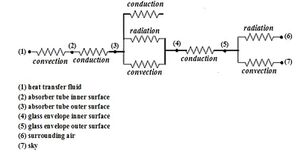
Thermal analysis means the heat loss or heat gain between the heat transfer fluid, receiver tube and glass envelope. The conductive, convective and radiative losses are offered by the heat transfer fluid, absorber and receiver tubes and the ambient. A total of eight resistances exist between solar radiation and the heat transfer fluid out of which three are convective, three are conductive and two are radiative. At typical operating condition, the flow in the heat collector element is well within the turbulent flow region. But during the off-sun hours the flow in the heat collector element may become transitional or laminar because of the viscosity of heat transfer fluid at lower temperature. The convection heat transfer mechanism between the absorber tube and glass envelope depends upon the annulus pressure. Since the pressure in the annulus is very less therefore we have selected vacuum condition in annulus where the heat transfer between the absorber and the glass envelope occurs by free molecular convection. Radiation transfer calculation is simplified by assuming glass envelope is opaque to infrared radiation and assuming gray surface (ρ=α) surfaces.
The anti-reflective treatment on the glass surface is assumed to have no thermal resistance. For convection heat transfer from glass to the sky, I have assumed no wind case. The overall heat transfer coefficient can be calculated by taking the reciprocal of the total resistance.
The thermal resistance network below shows the resistance that are offered by heat transfer fluid, absorber and receiver tubes and the ambient.
While carrying out thermal analysis, following calculations were performed:
- Heat transfer between inner absorber tube and heat transfer fluid
- Heat transfer between inner and outer absorber tube surface
- Heat transfer between outer absorber tube surface and inner glass envelope surface
- Heat transfer between inner and outer surface of glass envelope
- Heat transfer between glass envelope and atmosphere
- Overall heat transfer coefficient
Design of PTC[edit | edit source]
A solar thermal parabolic trough collector can be used to harness solar energy at rather higher temperature depending on the working fluid used. The parabolic curve would focus all the rays to a focal point, and a trough normally extends the shape in three dimensions to turn the focal point into a focal line. The receiver is placed concentrically along this focal line, as its axis. A rim angle of 80 degree is considered as it gives an optimum intercept factor. The reflecting surface on the parabolic surface should have a very good specular reflectance. Diameter of trough was determined to be 1.25m from mathematical formulations.
Performance Evaluation and Solar Area of PTC[edit | edit source]
Performance evaluation of PTC was carried out considering:
- Overall heat gain
- Heat removal factor
- Absorbed solar radiations
- Optical efficiency of receive tubes
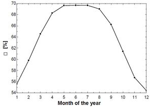
Thermal efficiency of the PTC refers to the ratio of useful energy delivered or collected to the insolation incident on the receiver tube. The efficiency came out to be 55.62%. Graph below depicts change in efficiency due to different heat gains for different months across the whole year:
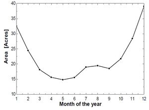
Also, calculations were performed for determination of number of collectors required, collectors spacing as well as the land required for the solar field. Total area required was found out to be 32.54 acres. Variation of solar area across the year is shown in the graph below:
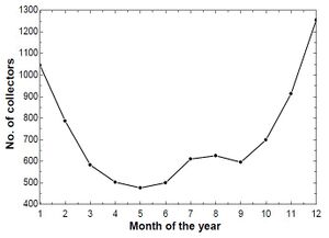
Considering the total energy requirement of approx. 20 MW, calculations showed that a total of 1045 collectors will be required. Since the number of collectors also vary with heat gain per PTC, hence, for other months of the year the graph for number of collectors is illustrated below:
Fresnel Collector[edit | edit source]
Fresnel and parabolic both are line focusing collector. Linear Fresnel reflector technology relies on an array of linear mirror strips which concentrate light on to a fixed receiver mounted on a linear tower. Fresnel mirror are based on linear solar concentration. The linear concentration is one whose concentration is based on a line. Concentration depends on the mirror surfaces and receiver area. But if the mirrors are fixed, it will reach its maximum at a specific time of day and will decline around this time. To limit this decrease most systems have a mechanism to track the sun. The orientation is tailored to optimize the position of the reflecting surface relative to the sun.
As the sun's position is characterized by two values: height ranging from 0 to 90 °, and azimuth ranging from -180 ° to +180 °, two orientation axes of the mirrors meet the monitoring purpose. Fresnel collector uses flat mirrors whose slope varies according to the position of the sun to focus radiations onto the receiver. Another mechanism of fixed reflection redirects the radiation towards the receiving tube. Fresnel collectors have lower efficiency than parabolic trough.
The greatest advantage of Fresnel reflectors is that they use flat reflectors which are cheaper and secondly they are mounted close to the ground thus minimizing structural requirements.
Performance Evaluation and Solar Area of Fresnel Collectors[edit | edit source]
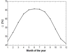
Using analogous formulations as for PTC, efficiency of Fresnel Collectors was determined to be 47.36%. The efficiency due to different heat gains for different months of the year is plotted in figure:
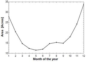
Calculations for solar area manifested 27.95 acres of space required for Fresnel Collectors. For the whole year, area requirements are illustrated in the line graph below:
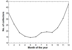
And number of collectors required were evaluated to be 35. The number of collectors vary with the heat gain per collector, hence, for other months number of collectors required are depicted in the graph below:
Furthermore, designing of secondary reflectors was also performed for Fresnel Collectors. The purpose of secondary reflector is to direct solar radiations onto receiver tube and thus maintain a homogenous temperature. Secondary reflectors are two parabolas which focus radiations reflected by the primary mirrors which are not intercepted by absorber tube, onto the top half of absorber tube. The parabola on the left side directs the radiations reflected from the right side primary mirrors, onto the top half of the tube while the right side parabola reflects the radiations reflected from the left side primary mirrors onto the top half of parabola.
Comparison of PTC and Fresnel Collector[edit | edit source]
The graph between collector efficiency and month of year for both collectors is shown below. It illustrates that the collector efficiency of parabolic trough collector is greater than linear fresnel collector because of high optical and thermal losses of linear Fresnel collector.

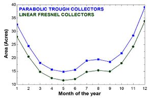
This graph below depicts that the total area required by parabolic trough collector is greater than Fresnel collector due to more collector spacing because of greater shadow.
Heat Exchangers[edit | edit source]
I have used two shell and tube exchangers in my design. One exchanger is used to change the phase of water at 8 bar pressure with fluid (Syltherm oil) which is coming from collector at 400ᵒC. This exchanger is called evaporator. Then hot fluid travels to the feed water heater which increases temperature of tap water to 400ᵒC. After that, Syltherm oil at 100ᵒC travels back to collectors. Shell and tube type exchangers are used as they are widely employed in the industries.
For the designing of heat exchanger I have used kern method. The heat exchangers are 80% efficient operating at 8 bars pressure with tube inner diameter of 0.017m (1/2 in). The flow rate of steam required at the exit of the heat exchangers is 6.11 kg/s and for this purpose, the HTF flow rate through the tubes is calculated to be 40.92 kg/s.
Results of calculations for both feedwater heater and steam generator indicated that feed water heater is a 166 tube, 4 pass, with a shell diameter of 0.99 m and tube length of 6.6 m heat exchanger, providing an overall heat transfer of 4.67 MW converting the sub cooled water to saturated water. While the steam generator is a 198 tube, 4 pass, with a shell diameter of 1.1 m and tube length of 9.93 m heat exchanger, providing an overall heat transfer of 15.60 MW converting the saturated water coming from feed water heater to saturated vapor.
Conclusion[edit | edit source]
The study projects an application of solar thermal energy towards minimization of the ongoing energy crisis in the country. It presents two types of solar collectors namely Parabolic Trough Collectors and Fresnel Collectors, which according to Soteris(4) are the two most feasible methods for industrial process heat generation. Both the collectors are modeled both optically and thermally and a detailed analysis of required land area is also done. Finally for heat exchange with water, heat exchangers are also designed.
As shown by the calculations, the efficiency of Parabolic Trough Collectors is higher than that of Fresnel collectors, however, since the inter collector spacing of Parabolic Troughs is greater and the Fresnel collectors have a greater covered land area, therefore the land area required for Parabolic Trough Collector technology is also higher, which can add to the cost of PTC technology.
As a case study for the purpose of this project, a textile industry situated in Karachi was chosen for which saturated steam with a flow rate of 22 tons per hour at 8 bars pressure was required. The study suggests that a solar field with 43 linear Fresnel reflectors or 1260 parabolic trough reflectors will be required to meet the total thermal energy demand of 20.1 MW throughout the year.
References[edit | edit source]
- Diffuse Solar Radiations From Sunshine Hours And Clearness Index For Karachi. Firoz Ahmad, Aqeel Burney. 1990.
- Performance Of A Parabolic Trough Collector. Brooks, Micheal. 2005.
- Diffuse Solar Radiation Estimates From Sunshine Hours And Clearness Index For Karachi. Firoz Ahmad, Aqil Burney. 1990.
- The Impact Of Energy Crises On The Textile Sector Of Pakistan. Shah, Beenish. Journal Of Emerging Issues In Economics, Finance And Banking (Jeiefb).
- Industry, Ministry Of Textile. Textiles Policy 2014-19. 2014.
- Exploring Perceptions Of Employees On Possible Effects Of Energy Shortage On Textile Industry- A Case Study. Yousaf, Rana Muhammad. 2014.
- A Linear Parabolic Solar Trough Performance Model. Ming Qu, David Archer And Sofie Masson.
- Test Results Seg Ls-2 Solar Collectors. Dudlry, Vernon E. 1994.
- Heat Transfer Analysis And Modelling Of A Parabolic Trough Solar Receiver Implemented In Ees. Forristall, R. 2004.
- An Optimized Model And Test Of The China’s First High Temperature Parabolic Trough Solar Receiver. Gong, Guangjie. 2010.
- A., Cengel Yunus. Heat And Mass Transfer.
- Company, Dow Chemical. Syltherm-800, Heat Transfer Fluid.
- John A. Duffie, William A. Beckman. Solar Engineering Of Thermal Processes.
- Heat Transfer Analysis Of Parabolic Trough Solar Receiver. Ricardo, Gokmen, Yogi, Elias And Rahman.
- Optical And Thermal Modelling Of Parabolic Trough Concentrator Systems. Wirz, Men.
- Frank P. Incropera, David P. Dewitt. Introduction To Heat Transfer.
- Exploring Perceptions Of Employees On Possible Effects Of Energy Shortage On Textile Industry- A Case Study. Yousaf, Rana Muhammad. 2014.
- Energy Assessment Of Parabolic Trough Collectors In North Cyprus. Soloman, Olopade. 2011.
- Thermal And Thermodynamic Analysis Of Parabolic Trough Receiver At Different Concentration Ratios And Rim Angles. Mwesigye A., Meyer J.P. 2014.
- Comparison Of Different Heat Transfer Models For Parabolic Trough Solar Collectors. Hangbo Liang, Haun Zhang. 2015.
- Optical Characterization Parameters For Line Focusing Solar Collectors: Measurement Procedures And Extended Simulation Results. Osorio, P. Horta And T. 2014.
- Performance Enhancement Of Parabolic Trough Collectors By Solar Flux Measurement In Focal Line. Klaus Jurgen Rifflemann, Andreas Neumann. 2006.
- Designing A Solar Thermal Parabolic Trough Collector By Simulation. Singh, Balbir.
- A Comparative Study Between Parabolic Trough And Linear Fresnel Reflector Technologies. Ghabri, Najla El.
- Solar Thermal Collectors And Applications. Kalogirou, Soteris A.
- Comparison Of Linear Fresnel And Parabolic Trough Collector Powerplants.
- Comparison Of Linear Fresnel And Parabolic Trough Powerplants. Morrin, Gabriel