Introduction[edit | edit source]
With the increase of global food demand, is is becoming more of a necessity to shift towards sustainable farming methods. Seaweed farming has been developed to be an extremely quick and nutritious solution to feeding growing communities (WWF - Farmed Seaweed). Generally, these farms are easy to maintain, require little fertilization, pesticide use, and watering, and yield considerable crop sizes (WWF - Farmed Seaweed). By 2012, the international production of seaweed farms reached 24 million tons, and is steadily growing currently (Chapter 3 - Farming of seaweeds). The method for growing seaweed is generally akin to draping a long polypropylene or nylon rope across a body of water and tying an initial 50-100g seaweed sample to the rope (Seaweed carrageenans: Productions and applications - ScienceDirect). The need for extra long and cheaply made, but adequate quality rope is becoming a major necessity in the industry.
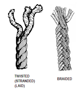
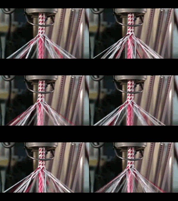
The general idea of rope is millenniums old, with the first documented case approximately 28,000 years ago with plant fibers forming the structure (History of Rope). As seen in figure 1, there are two major divisions of rope design: twisted or braided ropes. Twisted ropes are the more traditional type of rope and have been around since medieval times (Medieval Rope Making). They are made by clamping a group of fiber strands together on one end and rotating the other end until the rope is wound tightly. To prevent the structure from unravelling when unclamped, the individual strands are counter spun to be 45 degrees from the horizontal to balance out the stress. As seen in figure 1, the fibers are oriented in parallel with the rope structure, so no internal force would exist to cause an unravel. Twisted rope is generally less flexible and weaker than braided rope. They also stretch more and tend to kink more often than braided rope. To make extremely long twisted ropes, the industry has developed very long structures called ropewalks that are capable of producing quarter-mile (220 meter) long twisted ropes in the traditional way (Insider). More compactly, the devices used to produce braided rope were designed to produce large quantities of rope in a stationary fashion (see figure 2 for a closer look of the mechanics of the braid). Braided ropes are also used more in industry currently. This is partly due to its preferred characteristics when compared to twisted rope. They are more flexible, stronger, stretch less and have a more smooth feel when compared to the traditional rope design
Design[edit | edit source]
From initial research, it became clear that designing a machine that produces braided rope would require less space, allow longer ropes to be produced, and have better characteristics for use in seaweed farming. The machines used to manufacture braided rope are much more compact, and can produce rope as long as there are input strands being fed through it. From looking at currently produced machines, a few common trends emerged that would guide the development of this device. Firstly, the braiding process is a vast topic; different companies produce machines that braid rope differently than others. In this review report, the Legare Knitting Machine, I-cord Knitting Machine, and the Addi Egg knitting machine will be reviewed and will inspire aspects of the final design.
All of these designs have very similar hook motion, that can be broken down into four separate phases, as per Andre Bandarra's youtube video at the 5 minute mark:
- The pulldown, where it hooks the strand and brings it under the previous strands.
- The pushup, where it pushes the strand behind the vertical pegs.
- The push-out, where the hook comes down, but instead of hooking it, the angle of the outside props the strand out for use in the next phase, and
- The push-over, where the strand gets picked up by the edge of the hook and is propped over to go through the center hole.
Mechanics[edit | edit source]
The hooks are designed in such a way as to move between two guide rails that push either up and down to perform the four phases of hook motion as described above. The guides were designed at an angle of 45 degrees to minimize friction between the hook peg and the surface, to make motion as fluid as possible. A steeper angle was originally planned to allow as much displacement of the hooks as possible, but this configuration had too much friction and the cylinder would not turn.
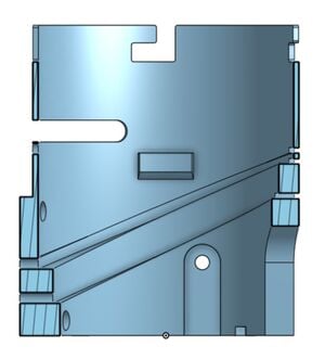
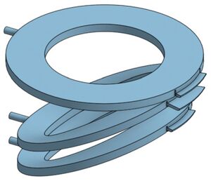
The guide rails were designed to be easily slipped into their designated positions for quick replacement if broken during operation. To install the guide rails (as seen in figure 4), simply slip the hook guide pins into the designated holes in the outer cylinder (figure 3) and push down firmly to lock the other side into their designated slots.
Printing guide: To print the rails, it is best to place them parallel to the bed and use supports as they are not perfectly flat. I suggest using a top contact Z distance of at least one full layer, and an XY separation of 50% or greater for easy removal of support material. I also suggest using a 15% rectilinear infill with monotonic top and bottom layers. All other settings are up to user preference.
Hook Design[edit | edit source]

The design of the hooks (as seen in figure 5) involve adapting existing knitting machine hooks for use with 3D printed parts. The precision and strength required by the knitting process make designing fully 3D printed hooks difficult. The hooks must have minimal friction as to allow the rope to move freely over it, which translates to designing a very thin shaft that has minimal contact area. The consequence of this approach is the hook being weak and snap when force is applied by the strands. The determined solution was using steel hooks and designing an adapting piece that works with the guide rails.
To install the hooks into the current design, simply insert into their designated holes from the bottom when the top plate is not locked in place.
Printing guide: Print with user preferred settings.
Motor[edit | edit source]
For the purposes of this project, it was found to be beneficial to use a stepper motor. This decision stems from the benefits the motor provides. Stepper motors are low wear, high torque, and can run continuously for long periods of time. (Stepper motor). This device will be running for extended periods of time to produce long ropes, meaning it has more oppourtunity to generate heat during operation. The brushless motor is designed to have minimal heat generated and wear, to allow the design to perform optimally for longer.
The motor used in this design is the NEMA MS17HD6P4100. Which has a 0.63Nm holding torque, 1.8 degree step size, 1A rated current, and 25mNm detent torque. The motor is controlled with an A4988 driver chip, and can be controlled by adapting the following code as provided by MakerGuides.com. This code alternates the stepper motor going clockwise and counter-clockwise. To change the direction of the motor, dirPin is either set HIGH for clockwise or LOW for counter clockwise. To change the speed of the motor, simply change the parameter in delayMicroseconds(x). The pin out of the motor is seen in the following datasheet, which is the online datasheet, as provided by Moons.
/*Example sketch to control a stepper motor with A4988 stepper motor driver and Arduino without a library. More info: https://www.makerguides.com */
// Define stepper motor connections and steps per revolution:
#define dirPin 2
#define stepPin 3
#define stepsPerRevolution 200
void setup() {
// Declare pins as output:
pinMode(stepPin, OUTPUT);
pinMode(dirPin, OUTPUT);
}
void loop() {
// Set the spinning direction clockwise:
digitalWrite(dirPin, HIGH);
// Spin the stepper motor 1 revolution slowly:
for (int i = 0; i < stepsPerRevolution; i++) {
// These four lines result in 1 step:
digitalWrite(stepPin, HIGH);
delayMicroseconds(2000);
digitalWrite(stepPin, LOW);
delayMicroseconds(2000);
}
delay(1000);
// Set the spinning direction counterclockwise:
digitalWrite(dirPin, LOW);
// Spin the stepper motor 1 revolution quickly:
for (int i = 0; i < stepsPerRevolution; i++) {
// These four lines result in 1 step:
digitalWrite(stepPin, HIGH);
delayMicroseconds(1000);

digitalWrite(stepPin, LOW);
delayMicroseconds(1000);
}
delay(1000);
}
Strand Feeder[edit | edit source]
The strand feeder mechanism, as seen in the figure 6, was designed to be replaceable and use as little material as possible. Its purpose is to guide the input strand into a retracting hook. To install, simply place the bottom cylindrical portion of the part into the designated hole in the top locking plate and insert a small piece of filament through the hole to secure.
Printing guide: To print, it is best to print with monotonic layers, 15% infill, and use supports with one layer top Z contact distance and 50% XY separation. It can be printed with either PLA or PETG.
Spooler[edit | edit source]
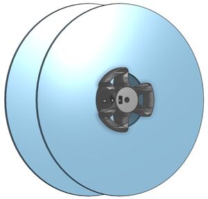
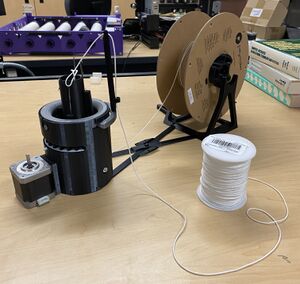
The spooler is designed to collect the finished product and provide constant tension for the weaving to properly occur. The spooling frame is connected to the main body with the use of a cross bar connector that keeps the structure rigid (as seen in the mechanical design of device photo at the top). The motor is mounted on the exterior of the frame using the top screw holes, and then attached to the clamping spool rod by a set screw mechanism (as seen in Figure 7). The frame, rod and nut all can be printed using user preferred settings with no supports required.
Future Work[edit | edit source]
The following file is a self winding spool on thingiverse that would allow the rope to properly wind around the spool: Thing files for DIY Winding machine with self reversing screw by electricdiylab - Thingiverse
** As for the operation of the device, the rope weaving technique requires slight 'tugging' of the rope to ensure the strands pop over the hooks and into the centre shaft. Significant testing and tuning will be required to determine the optimal pressure/ timing of the secondary spool motor for continuous operation of the device.**
Other Resources[edit | edit source]
- How Rope is Made: History, Manufacturing, Types - Quality Nylon Rope
- How Rope is Made - Rope and Cord
- Instructable how to make rope guide
- DIY Rope making machine
- Inside a traditional rope making factory video
- Braided Rope Arduino Robot video
Onshape Link[edit | edit source]
This is a project page of the Rope Winding Robot, as designed by Logan Derry under FAST Labs at Western University
Warning: Display title "" overrides earlier display title "Automated Rope Braiding Device".
