
The goal of this project is to create a simple, inexpensive real time LiDAR mapping solution that can be easily implemented in a variety of use cases.
Background and Problem Statement[edit | edit source]
In the world of robotics and 3D mapping, LiDAR technology is fast becoming industry standard. Compared to RADAR, the lower wavelength used allows LiDAR to hold a higher standard of accuracy and precision. Many market solutions for LiDAR systems however, are complex, expensive, and proprietary. The goal of this project is to create an LiDAR system that is accessible from both a cost and complexity standpoint.
Vision[edit | edit source]
To realize this LiDAR system, the following goals were put into place.
- The project must be simple and have a low barrier to entry
- The code that runs this system must be as simple as possible and be well documented
- Any parts created must be easily 3D printed and assembled
- The cost to build this system must be $100 or less
- The system must be open source; it must be easily replicated and changed by end user to fit given use case
A set of engineering requirements were also defined for this project.
- The motor must achieve a speed of at least 60 RPM
- The range of the system must be at least 10 meters
- The system must have an accuracy of at least 5 cm at maximum range
- To reduce points of failure and increase accuracy, the system must be contained in a single cylindrical enclosure and the laser and receiver must be driven directly
- The system must know it's own position and which direction is forward. (absolute position)
Research and Design[edit | edit source]

To fulfill our engineering requirements, we chose to use the TF Mini-S LiDAR module. According to the data sheet, this module is capable of measuring with an accuracy of ±6cm between 0.1m and 6m, and ±1% between 6m and 12m at a rate of 1-1000 hz. In our research, we found that this module best fits our use case as it fulfills our requirements (detailed above) and only costs around $40.
To rotate the LiDAR module, a Nema 17HS-13 stepper with DRV8825 driver board was chosen. This combination of hardware was chosen because the motor can provide enough rotational velocity and torque to meet our design requirement and the DRV8825 board allows for external motor control by our main microprocessor. Another popular driver board, the A4988 board, would also function for this use case, but we chose the DRV8825 because it is able to handle higher currents without a larger heatsink. Choosing an external driver board ensures that the bulk of the processing capability of the main microprocessor can be allocated to the LiDAR module. We plan to use a slip ring to route the cables through the stationary portion into the rotating portion of the final enclosure.
To run the entire system, an Arduino Nano was chosen. This microprocessor was chosen as it is small and inexpensive, but has enough power and pins to drive every component. The Nano will be easy to fit into the final enclosure while still having enough processing power to gather the necessary data from the LiDAR module.
To determine the position of the sensor relative to the stationary enclosure a system was developed using a photoresistor and an LED. The LED would be mounted to the rotating part that held the sensor, while the photoresistor would be in the bottom cylinder that holds the motor itself. As the LED passes by the photoresistor the system would reset the angle to 0 degrees, therefore setting that position as forward.
Validation[edit | edit source]

To validate that the LiDAR module was functioning correctly, we used the TF-GUI software provided by the manufacturer of the LiDAR module. When the module is functioning properly, the output distance of the sensor is displayed in the software. We were able to validate the accuracy and frequency of the measurements provided by the module using this software.
When the system was initially designed, a smaller 28BYJ-48 Series stepper motor was chosen. This motor however was unable to meet the speed that was chosen in the engineering requirements. Furthermore, the ULN2003A driver board which is used to drive this stepper motor required the computation of acceleration and velocity onboard the Arduino. Because of this, the Arduino began to have trouble driving the stepper motor while simultaneously collecting data from the LiDAR module. To fix this problem, the Nema 17HS-13 stepper motor paired with the DRV8825 driver was chosen. Compared to the ULN2003A, the DRV8825 handles much more of the motor computation. Furthermore, the Nema 17HS-13 is a common and versatile stepper motor that exceeds the speed requirement, while still being inexpensive.
Major Component: Slip Ring[edit | edit source]
In our original design we planned on buying a slip ring to incorporate into the housing. After reviewing the vision of the project we realized that the original slip ring that we thought to purchase would not fit our use case; we needed to get a through-hole slip ring rather than a standard one. These through hole slip rings are more specialized and generally more expensive than a standard slip ring. As such 4 wire through hole slip ring did not fit the $100 budget of the project. In light of this new information we decided to design our own slip ring that could be 3D printed.
Final Design[edit | edit source]
All the files and code needed to replicate this project can be found here:
https://github.com/kevinfogg/OSHE-LiDAR
To begin assemble the Slip Ring
Materials: 3/8 copper coupling union, soldering iron, 18 awg wire, 22 awg wire
3D Print: Frame V2 or Frame V2 Top, Slip Ring - Inside, and Slip Ring - Outside
1) cut the 3/8 copper coupling into lengths of ~2.4 mm. You will need 4 'rings' cut out. Sand the cut edges flat and smooth.
2) Strip one side of a wire and feeding it through one of the 4 holes in the top 3D printed piece so that the stripped end is on the side with the post.
3) take the stripped side of the wire and solder it to the inside of one of the rings cut out from the copper coupling. It should be soldered so that the wire and ring can be slipped over the post with the wire fitting completely into the groove.
4) add one of the printed washers on top of the ring.
5) repeat steps 3 and 4 for the second, third, and fourth ring.
6) Take about 7 inches of 18 gauge wire and wrap it around the slip ring. leaving the excess wire on both sides of the inner ring. Strip the wire in the center for the length that it takes to wrap around the copper ring plus a half-inch. This is so that once the wires are run through the outer housing, they can be tensioned by twisting them together.
7) prepare 4 wires in the way described in step 7.
8) feed the four newly prepared wires through the two holes on the bottom half of the slip ring, leaving the loop that is created with as much extra length as possible out of the top of the hole where the top of the slip ring piece fits.
9) place the wires over their corresponding copper rings and pull them tight together as you feed the top piece of the slip ring into the bottom piece.
10) Place the assembled slip ring onto the top plate of the housing and the Nema-17 motor below the top plate. Use 4 m3 4 mm bolts to attach the motor, housing and slip ring together.
11) take the wires that wrap around the inner copper rings and should currently be hanging out of the side of the slip ring, and twist them together with themselves to take the slack out of the wires on the inside.
12) to ensure proper connection, check the wires out of the side of the slip ring and the top wires for continuity with a multimeter
Assemble the rest of the system:
- 3D Print the remaining parts
- Gather the rest of the components per the bill of material.
13) Assemble the circuit board according to the schematic
14) If the frame was printed in 2 parts, glue the top and bottom together
15) Glue the circuit board to the base ensuring that the ports on the board are oriented correctly
16) Plug the stepper motor, slip ring and photoresists into the board
17) Glue the frame to the base
18) Connect the TF mini and LED to the top of the slip ring
- Assembly Images
-
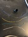
Step 6: 18 awg Wire Prepared for Slip Ring
-
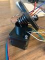
Step 9: Slip Ring in Position to be Assembled
-
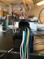
Step 11: Wires Wrapped Together
-
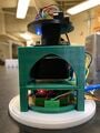
Final Assembly


Proof Testing[edit | edit source]
After designing the slip ring we had a few ways to ensure that it would actually function. We started by taking a multimeter and checking for continuity between the wires when the slip ring was not spinning. After passing that test we moved on to connecting two of the wires on the top and turning the motor on. We then checked continuity between those two wires while spinning at expected "full" speed of our device. The final test we did before testing it with the LiDAR sensor was attaching the wires to a function generator and an oscilloscope. We then input a square wave through the wires and measured the output on the oscilloscope while the motor was stationary. We then repeated the test while the motor was spinning and compared the measurements on the oscilloscope. When these tests were passed we connected the LiDAR sensor and tested actual data transmission while stationary and while spinning.
Semester Progress[edit | edit source]

| Hardware | Software |
|---|---|
|
|
During the past month, all of these goals were fulfilled.
print PCB and connect all electronics. When our design was finalized on the bread-board, we decided to design a PCB to make the LiDAR Bot a more refined product and to get experience working with PCB design software. The PCB was designed to be effectively one layer and in a footprint that is not much larger than the motor size. These choices were made to make the product as compact as possible as well as cheap to replicate if you had to order the PCB.
- final assembly
- Software: Pinpoint direction system. One of the troubles we ran into was how to determine cardinal direction on the device. We had to make sure that each time the device turned on there was a defined 'forward' direction. The way we implemented that system was to embed an LED into the spinning portion of the housing behind the LiDAR sensor. Under the spinning portion, in the housing, is a photoresistor to detect when the LED passes directly over. When the LED and photoresistor are overtop of each other the Arduino Nano fires an interrupt that resets the value in the code associated with the angle of the motor.
Bill Of Materials[edit | edit source]
To build LiDAR Bot, the following parts are necessary:
| Name | Quantity | Cost |
|---|---|---|
| TFmini-s Micro LiDAR Module | 1 | $39.09 |
| Nema 17hs13 Stepper Motor | 1 | $10.99 |
| Stepper Motor Controller DRV 8825 | 1 | $7.99 |
| PLA Filament | 1 | $19.99 |
| Arduino Nano | 1 | $9.99 |
| Photoresistor | 1 | $.95 |
| 10K Ohm resistor | 1 | $0.50 |
| 100 μF Capicator | 1 | $.93 |
| 12 volt .5 amp power supply | 1 | $5.99 |
| 3/8 Copper slip union coupling | 1 | $1.79 |
| M3 4mm bolts | 4 | $0.50 |
Project Total: $98.71
Assembly[edit | edit source]
To build the current version of the LiDAR Bot, the above components may be assembled on a breadboard according to the following schematic. Before the system can be run, ensure that the stepper driver current limit is set correctly by following these instructions.

The connections are as follows:
- TFmini-S LiDAR Module
- Tx (green) connected to Arduino pin D6
- Rx (white) connected to Arduino pin D7
- +5V (red) connected to Arduino 5 volts
- Gnd (black) connected to Arduino ground
- DRV 8825 Stepper Motor Controller
- VMOT connected to +12 volt power supply
- GND (immediately below VMOT pin) connected to -12 volt power supply
- SLP connected to Arduino 5 volts
- RST connected to Arduino 5 volts
- GND connected to Arduino ground
- DIR connected to Arduino pin D4
- STP connected to Arduino pin D5
- A1 connected to inductor 1 of the stepper motor
- A2 connected to inductor 1 of the stepper motor
- B1 connected to inductor 2 of the stepper motor
- B2 connected to inductor 2 of the stepper motor
- 100 μF capacitor
- Connected between the positive and negative sides of the 12V power supply
- Photoresistor
- Connected between Arduino pin D2 and 5V
- 10K Ohm Resistor
- Connected between Arduino pin D2 and Arduino GND
Code[edit | edit source]
In the old version, seen below, this code outputs the reading taken from the LiDAR module paired with the angle of the stepper motor relative to its starting position to the serial monitor of the Arduino IDE. This code only uses one Arduino to read and output the data.
# include <SoftwareSerial.h> //header file of software serial port

SoftwareSerial Serial1(6, 7); //define software serial port name as Serial1 and define pin6 as RX & pin7 as TX

int dist;					 //actual distance measurements of LiDAR
int strength;				 //signal strength of LiDAR
int check;					//save check value
int i;
int uart[9];				 //save data measured by LiDAR
const int HEADER = 0x59;	 //frame header of data package

// Define pin connections & motor's steps per revolution
const int dirPin = 4;
const int stepPin = 5;
const int stepsPerRevolution = 200;

int stepLocation;


void setup()
{
 Serial.begin(9600);		 //set bit rate of serial port connecting Arduino with computer
 Serial1.begin(115200);	 //set bit rate of serial port connecting LiDAR with Arduino

 // Declare pins as Outputs for NEMA
 pinMode(stepPin, OUTPUT);
 pinMode(dirPin, OUTPUT);

 digitalWrite(dirPin, HIGH); //set direction to clockwise

 attachInterrupt(digitalPinToInterrupt(2),ledSensed,RISING);
}

void ledSensed() {
 stepLocation = 0;
}

void loop() {

 for(int x = 0; x < stepsPerRevolution; x++)
 {
 	 stepLocation++;
 	 digitalWrite(stepPin, HIGH);
 	 LiDARMeasurement(stepLocation);
 	 delayMicroseconds(750); //best found so far to be delay of 750 micro sec
 	 digitalWrite(stepPin, LOW);
 	 LiDARMeasurement(stepLocation);
 	 delayMicroseconds(750);
 } //for loop

}

void LiDARMeasurement(int x){
 	 if (Serial1.available())				//check if serial port has data input
 	 {
 		 if (Serial1.read() == HEADER)		//assess data package frame header 0x59
 		 {
 			 uart[0] = HEADER;
 			 if (Serial1.read() == HEADER)	 //assess data package frame header 0x59
 			 {
 				 uart[1] = HEADER;
 				 for (i = 2; i < 9; i++)		 //save data in array
 				 {
 				 uart[i] = Serial1.read();
 				 }
 				 check = uart[0] + uart[1] + uart[2] + uart[3] + uart[4] + uart[5] + uart[6] + uart[7];
 				 if (uart[8] == (check & 0xff))		//verify the received data as per protocol
 				 {
 				 dist = uart[2] + uart[3] * 256;	 //calculate distance value
 				 Serial.print(dist);				 //output measure distance value of LiDAR
 				 Serial.print(", ");
 				 Serial.print(1.8 * x);			 //output angle
 				 Serial.print('\n');
 				 }
 			 }
 		 }
 	 } //if serial.avaliable
}
Code with I2C communication[edit | edit source]
In the current of the code, the Arduino Nano sends the received information over I2C protocol to a receiving Arduino. The code for both the Arduino connected to the LiDAR and the Arduino that receives/outputs the information can be found below.
// Last Modified: 4-22-2022
// Last Uploaded to Device: 2-28-2022
// Code for the device directly connected to the LiDAR module and stepper motor driver
#include <SoftwareSerial.h> //header file of software serial port
#include <Wire.h>			 //include wire library for i2c communication
SoftwareSerial Serial1(6, 7); //define software serial port name as Serial1 and define pin6 as RX & pin7 as TX

int dist;					 //actual distance measurements of LiDAR
int strength;				 //signal strength of LiDAR
int check;					//save check value
int i;
int uart[9];				 //save data measured by LiDAR
const int HEADER = 0x59;	 //frame header of data package

// Define pin connections & motor's steps per revolution
const int dirPin = 4;
const int stepPin = 5;
const int stepsPerRevolution = 200;

int stepLocation;


void setup()
{
	Serial.begin(9600);		 //set bit rate of serial port connecting Arduino with computer
	Serial1.begin(115200);	 //set bit rate of serial port connecting LiDAR with Arduino

	// Declare pins as Outputs for NEMA
	pinMode(stepPin, OUTPUT);
	pinMode(dirPin, OUTPUT);

	digitalWrite(dirPin, HIGH); //set direction to clockwise

	attachInterrupt(digitalPinToInterrupt(2),ledSensed, LOW);

	 Wire.begin();	 //set up pin 8 for i2c
}

void ledSensed() {
	stepLocation = 0;
}

void loop() {

	for(int x = 0; x < stepsPerRevolution; x++)
	{
		stepLocation++;
		digitalWrite(stepPin, HIGH);
		LiDARMeasurement(stepLocation);
		delayMicroseconds(750); //best found so far to be delay of 750 micro sec
		digitalWrite(stepPin, LOW);
		LiDARMeasurement(stepLocation);
		delayMicroseconds(750);
	} //for loop

}

void LiDARMeasurement(int x){
		if (Serial1.available())				//check if serial port has data input
		{
			if (Serial1.read() == HEADER)		//assess data package frame header 0x59
			{
				uart[0] = HEADER;
				if (Serial1.read() == HEADER)	 //assess data package frame header 0x59
				{
				 uart[1] = HEADER;
				 for (i = 2; i < 9; i++)		 //save data in array
				 {
					uart[i] = Serial1.read();
				 }
				 check = uart[0] + uart[1] + uart[2] + uart[3] + uart[4] + uart[5] + uart[6] + uart[7];
				 if (uart[8] == (check & 0xff))		//verify the received data as per protocol
				 {
					dist = uart[2] + uart[3] * 256;	 //calculate distance value
					Wire.beginTransmission(8); // transmit to device #8
					Wire.write(dist);
					Wire.write(x);
					Wire.endTransmission(); //
				 }
				}
			}
		} //if serial.avaliable
}
Code for the receiver device:
// This code is for the recieving info board
// Last Modified: 4-22-2022

#include <Wire.h>

void setup() {
	Wire.begin(8);				// join i2c bus with address #8
	Wire.onReceive(receiveEvent); // function that executes whenever data is received from writer
	Serial.begin(9600);
}

void receiveEvent() {

		int c = Wire.read(); // receive an int
		Serial.print(c); //print the distance measured
		Serial.print(" , ");

	 int x = Wire.read();
	 Serial.println(1.8 * x); //multiply the steps by 1.8 to make 360 degrees
}

void loop(){
}
References[edit | edit source]