Prior to installing the aluminium extrusion, properly been file down and debur edges to ensure proper mating of the extrusion and corner joints. Completing this will also help lower risk of exposing users to sharp edges on the robot itself.
The main chassis for GrowBot is built using only 3 main components: 30mm Aluminium Extrusion (187mm & 213mm lengths), Aluminium Corner Joints, and M5 Hex screws. The unit is designed to be modular and symmetric, giving the user ease of adapting different sensors and components into the chassis itself. This method of construction for the chassis ensures that the unit remains symmetrical, which is key for the autonomous functions of the robot in terms of keeping the robot on a straight path. The aluminium extrusion also offers t-rails which give the user an abundant amount of mounting positions an locations for those sensors and external attachments.
Begin by creating the top and bottom of the chassis.
To join the corner joints to a piece of 213 mm extrusion, slide the end of the joint into the t-rail of the 213 mm extrusion.
Slight pressure may be necessary to insert the corner joints to the t-rail, use the rubber mallet if necessary to press pieces in places.
Once inserted, place the 5mm hex screws into the threaded holes in the corner joint. Once threaded in, tighten the screw until slight pressure is applied from the joint to the extrusion, holding the pieces together.
Repeat this process 3 times to obtain the top portion of the chassis.
Repeat steps 2-4 to obtain the bottom portion of the chassis since they are symmetrical.
Once both portions have been obtained, take the 187 mm extrusion and place them vertically on the bottom portion of the chassis. Tighten the corner joints to these pieces as described in step 4.
After joining the vertical columns onto the bottom portion, slide the completed top portion onto the vertical columns, completing the union of the bottom and top chassis portions.
Tighten the final corner joint to these pieces as described in step 4.
Once the chassis has been completed, go back and tighten the rest of the 5mm screws until proper pressure is applied from the corner joints to the extrusion.
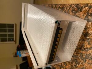
Assembling the PSU mount is the next step. This is mounted using the same set screws as the frame and can be mounted in any corner of your choosing, printed model may have to be changed to mimic which corner you would like. Current mount is in development and has not been mounted to the bot yet.