The beams are supposed to go on a specific way. Look at the images if need be if instructions seem unclear. Pay close attention to where the screw holes are for each beam!
Ender 3 baseOrientate the printer to look like how it looks in the image.
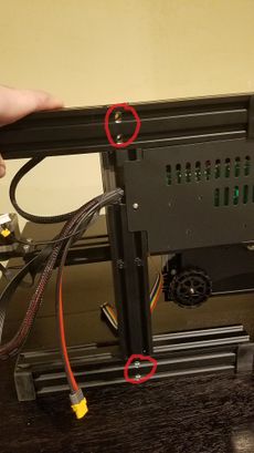
Ender 3 base tilted on its side. The red circles show where the M5x45 screws goTilt the Ender 3 base on its side. There are 4 screw holes on the bottom. The 20x40 beam with horizontal pre-drilled holes goes on the top side. The 20x40 beam with vertical pre-drilled holes goes on the bottom side.
Ender 3 standing up with both beams attached Notice where the drilled holes areThe horizontal pre-drilled hole beam should have the holes closer to the base. The vertical pre-drilled hole beam should have the holes one the side of the print bed and with the bottom hole closer to the base Use the reference image to see the end result. Both of these should be screwed on using the four M5x45 screws
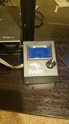
LCD screen with the ribbon cable attached to it Flip the LCD screen upside to see the circuit board. Facing the printer on the right, attach the ribbon cable to EXP3 slot.
Attaching the LCD to the base Align the screw holes with the LCD and screw it in using two M5x8 screws.
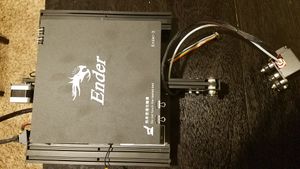
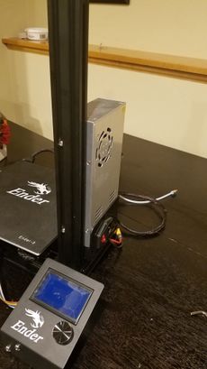
Attaching the power supply to the back of the vertical pre-drilled beam Taking the power supply, and two M4x20 screws, attach the power supply to the back of the vertical pre-drilled hole beam.
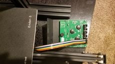
Attaching the Z-axis motor to the back of the horizontal pre-drilled beam Attach the Z-axis motor to the back of the vertical pre-drilled hole beam using two M4x18 screws.
If you are having issues with putting the screws behind the coupler, take the coupler off and then put it back on once you are done.
Inserting the Z-axis threaded rod Place the Z-axis threaded rod into the Z-axis motor coupler and then torque the top screw in the coupler tight. It will not work if the set screw is loose.
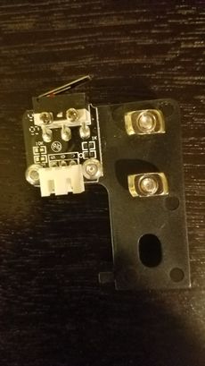
Orientating the t-nuts correctlyTake the Z-axis limit switch, and loosen it up enough for the t-nuts can fit in the side of the horizontal pre-drill beam. Make sure they are facing horizontal and not vertical. This may cause the limit switch to fall out of the beam.
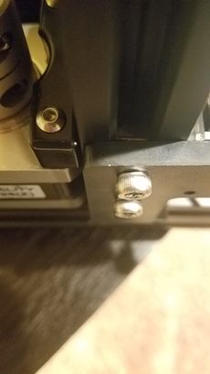
Placing the Z-axis limit switch in the horizontal pre-drill beam Take the Z-axis limit switch, and place the t-nuts through the slit in the beam. When t-nuts are through, gently bring it to the bottom making sure the t-nuts stay perpendicular with the slit. Tighten the screws when the limit switch hits the bottom.