
Anisa Foundation parabolic solar hot water heater

| Type | Solar hot water system |
|---|---|
| Authors | Frederick Lee Frazelle Anisa Foundation |
| Location | Mexicali, Baja California, Mexico |
| Status | |
| Years |
| Hardware license | CERN-OHL-S |
|---|---|
| Certifications |  Verify |
Our small team has been working on this project since December of 2011. We now have a working model but still need technical help in making it more efficient and in working out a few remaining challenges.
Temperature of the project displayed on the internet (https://thingspeak.com/channels/72565)
As of 6 Nov. 2016 this project has been certified as Open Source by the OSHWA (Open Source Hardware Association)! We are the only the second one in Mexico to be certified so far!
For additional information, please contact Fred Frazelle at info@fundacionanisa.org
Understanding the market
[edit | edit source]- We understand that these type of collectors can be used not only for heating water but for cooling (air conditioning) as well. The hot water produced can also be used for home/space heating purposes in the winter.
- This unit is being produced in northwestern Mexico, specifically in Mexicali, Baja California.
- Even though the climate is very hot here in the summers, there are many applications of this type of collector: swimming pools (for October through late April the water is too cold for swimming)j; home hot water use (for families larger than 4); industrial applications such as restaurants, hoteles; industrial processes.
- Later on we would like to adapt the units for cooling - home, hotels, industry, etc.
Project goals
[edit | edit source]Getting the project to the point where it can be produced and used and or marketed by small teams with little investment in tools or knowledge.
- Produce a manual - perhaps we can use this Wiki's "Create book" function.
- Obtain better collector measurements (See Discussion 10 April 2015)
- Obtain some sort of external approval. (See Project Status above - OSHW)
- Increasing the efficiency of the collector
- Overcoming some design problems:
- Mechanical placement of rotator arm - See "Rod Connection". See the motor area photos —I think we have this one solved.
- Getting the Mylar to lay flat and smooth - See the collector drawings. It appears that we now have this solved as well.
- Replacing the electronic board with either a Raspberry Pi + suitable program or at least in the beginning an electronic circuit which would be OpenSource
- Help maintaining this site - lol
- Using the Raspberry Pi (or other circuit) to collect temperature data and transmit it via WiFi for upload to internet. Pretty much accomplished! Yea! See link here [1]
- Translate the site into Spanish at least.
- The following is just my daily ToDo List...
- To update> Aluminum rod connection: replacement of Jalero; drawings
Design
[edit | edit source]- We have a prototype which produces hot water. As you can see from the photo the device is 8 feet by 40 inches. It swings about the 1.5 inch copper tube. From our rough calculations it produces about 1370 BTU at this point.
- The colector swing is produced by a small DC motor assembly which can be seen at the right of the collector.
- The collector orientation is controlled by a small, non-OS (OpenSource) electronic board and housing - about $48.00 U.S.
- The motor is capable of supporting about 5 - 6 colectors (we think)
-
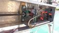 Motor and some wiring.
 -
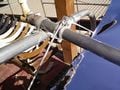 Jalero and water connections.
 -
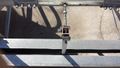 Aluminum Rod Connection.


Costs
[edit | edit source]At this point it appears that our cost is around $350.00 U.S. for the unit (collector and motor). This list is obviously not quite complete...
The costs include:
- 1.5" Electrical tubing for structure
- 1 sheet 4'x 8' Reflective Mylar
- Small DC motor
- 1 4' x 1' x 1' sheet metal box with lid
- 1 mm PET sheet, 8' x 4'
- 1 12' x 1/8" steel rod
- 1 SBE Digital Solar Tracker and housing
- Lots of assorted nuts and bolts - lol
- Wiring, including cabling
- 2 Pillow blocks for threaded rod
- Threaded rod - 1/2" x 4'
- Aluminum bar 1/4" x 1/4" x 8'
- Aluminum plates
- Stainless steel centerpiece
- Copper tubing 8' x 1.5"
Discussion
[edit | edit source]Please post any suggestions.
8 November 2016 We spent most of the last year trying in vain to get the sun tracker to track while mounted on the motor area. Finally decided to start to see if we could use the Raspberry Pi, Jay Dosher's Python program, a Python Sun Program and a 9 degree of freedom sensor to correctly orient the parabola. We got as far as debugging and porting Jay's program to Python 3.x, purchasing a stepper motor and actually seeing some of the output from the sensor on the monitor but since our background in electronics is non-existant, we never could get the sensor properly connected. We did get the Pi reading from a one-wire digital thermometer and uploading the data to www.thingspeak.com, which was a happy moment.
Eventally we decided to purchase the SBE Digital Solar Tracker and its enclosure (hopefully one of these days someone will build an Open Source tracker). We first placed it on the motor area. It worked. Then we transferred it to the upper left hand corner of the parabola. It seems to be working here as well, however we need to figure out how to affix it better and in order to test whether or not it is affected by reflections from the parabola itself, we need to redo the parabola surface.
Our most recent experiment for fabricating the parabola bed was to use a sheet of plastic PET, with the aluminized Mylar underneath it and to protect the PET, we got some anti-UV film and put it on top of the PET/Mylar sandwich. We got the Mylar to "stick" to the underside of the PET by just taping one long side and stretching it until taut. After almost a year in the sun we have discovered that the anti-UV stuff does not last and we have now scraped some of it off and pretty much smoothed the surface. This time we'll just maybe use 6 strips of two-sided tape to adhere the Mylar to the top of the PET and if we ever get to the place where we can sell these, we'll see if we can "sell" yearly maintenance contracts for $20.00 or so in order to be able to just replace the Mylar and tighten any nuts or bolts and generally just check the equipment and "touch base" with the owners.
5 October 2015 We turned the unit back on after staying off during the Summer. It was just too hot to work outside this year. After we turned it on, the next day we found that the unit went beyond the limit switch. Ug. It pulled the threaded rod from the left-hand pillow bearing. Good learning experience. We really need to make the limit switch finger longer.
We had covered the lower leds of the electronic seeker with short straws so that they would not be confused by the reflections coming off of the parabola. This seems to have solved this issue as well. The Lexan seems to be holding up very well. Yea!
We lost our swimming pool about a week ago, so we'll use the unit for home hot water...
i want to go back and check our drawings and photos to make sure that they faithfully reflect what we've put up so far.
10 April 2015 We finally got a new pump and were able to perform another test - we ran 50L of water through the system for six hours which produced 20 degree Celsius rise in the temperature which, according to our calculations is about 4,500 BTU. Can anyone tell us if this figure is correct?
The electronic solar tracker is still challenging - we tried an outdoor electrical glass dome, but it produced too much distortion for the LEDS. Switched to a Lexan locally produced box, but our glue didn't hold. Our son glued it again with a silicone gun and we think it's going to hold this time. It appears that Lexan needs a special kind of glue.
Now, we need to figure out how to shade this thing better since at 11 o-clock the LEDS begin to detect reflection coming off of the collector - lol - never a dull moment!
22 Jan. 2015 Well we went back to the iron rib strategy but this time we had the guy weld a bar the length of the ribs on either side. It made it a little difficult to transport back to the house, but it cost about the same as him making just the iron parabolic ribs, so it's good. We're back to this design bec. i think the three layer reflector will not now bend the ribs out of shape. The top of the ribs were secured with 3/4" aluminum channel and some small screws.
- We're still working with the UV/plastic sheet/Maylar combo until the next iteration but so far we have had better rain resistance (water doesn't seem to seep between the layers). We were going to try to calculate/estimate the efficiency of the system but we burned out the small pump and are waiting on the new one to arrive.
About the only other change is a small hole in the threaded rod of the motor assembly because the system was pulling the rod away from the motor - the set screws on the pillow bearing were just not holding - so we drilled a small hole through the rod and inserted a cotter pin.
- We also changed the location of the screw that holds the rotating arm to a lower position so that it more closely corresponds to the height of the collector tube height thereby creating a better parallelogram.
We also obtained a better circuit board for sun-seeking and are now using a glass bottle enclosure. We still need to add holes to the bottom of the jar and construct a different aluminum steadying plate for the circuit board.
18 October 2014 - We finally got the birch ribs cut, painted and separated using the shaft collars (kind of expensive little items...) and the 1/4" x 8' steel rods.
Since the Mylar doesn't hold up well if used directly outside in the sun, we have come up with what we think will be a good solution. We will try to put a layer of UV resistant film over our sheet of clear plastic (this is going to require figuring out how to use this type of film which is used for car windows, but on a surface which measures 4' x 8'). Then we will flip the plastic sheet and its film coating over and place on another set of ribs which have been inverted. Then we hope to be able to stretch the Mylar over the plastic sheet and secure with metallized tape. Then the whole sandwich can be flipped again and placed into the rib assembly. We think this idea should work since our son, Jalál, made the parabolic ribs with the same curvature on the inside as well as the outside. We'll see.
In the other section (Motor Area) we comment on how we think we have overcome the challenge of the motor area.
4 September 2014 Last week the unit lost its top two layers - the PET and the Mylar ones to a 67 Km. gust of wind during a rain storm. We took the bottom layer off and dismounted the metal ribs. When we examined them we found that they had bent outward slightly and have decided to try wood ribs again. We got a carpenter to fabricate new birch ribs and will be painting them and using two 1/4" x 8' steel rods and 1/4" x 1/2" x 9/32" shaft collars to separate the ribs. We are also trying to find 8' long aluminum channel for the rib ends.
30 April 2014 Connected system to Intex 15 ft. x 48 in. pool. We need to buy more insulation for the PVC tubing.
12:45 Air temp: 28 C, Pool temp: 20.3 C Winds: Brisk. Water depth: 3 ft. Yea!!
See also
[edit | edit source]Related projects
[edit | edit source]| Authors | |
|---|---|
| License | CC-BY-SA-3.0 |
| Organizations | Open Source Hardware Association |
| Cite as | Frazelle09 (2014–2025). "Anisa Foundation parabolic solar hot water heater". Appropedia. Retrieved July 7, 2026. |