| Line 221: | Line 221: | ||
{{How to | {{How to | ||
|title=How to Replicate RIPSAW | |title=How to Replicate RIPSAW | ||
|File:. | |File:tools_used.JPG||1 |Make sure to have all materials shown in '''[[A:BOLD|Description of Solution]]''': Level, Angle, Cordless Drill, Drill Bits, Ballpeen Hammer, Vise-Grips, Screwdrivers, Angle Grinder with wire and sandpaper wheels, Standard Wrench set, Standard 3/*' Socket set, 3/8" Socket Wrench, Tape measure, MIG Welder, Plasma Cutter, Band Saw and Wire Cutters | ||
|File:.jpg||2 |Measure all given metal components from the materials list to the lengths shown | |File:measuring_square_tubing.jpg||2 |Measure all given metal components from the materials list to the lengths shown below: '''[[A:BOLD|Square Tubing]]''': 2-3" sections, 2-17.7" sections, 2-14" sections | ||
|File:.jpg||3 |Weld 3" section of square tubing to c-channel | |File:.jpg||3 |Weld 3" section of square tubing to c-channel | ||
|File:.jpeg||4 |Weld 17.7" section vertical 90 degrees from the 3" section and 14" section horizontal 90 degrees to the 17.7" square tubing as shown }} | |File:.jpeg||4 |Weld 17.7" section vertical 90 degrees from the 3" section and 14" section horizontal 90 degrees to the 17.7" square tubing as shown }} | ||
Revision as of 22:38, 13 April 2014
Abstract
The purpose of this project is to design a safe bridge tester system that is able to measure the strength and endurance of bridges under pressure in pounds per square inch. Through the engineering 215 class at Humboldt state University, students from team Burke der Meister designed a bridge tester machine that will be integrated into the engineering section of the STEAM Program at Zane Middle school for projects and competitions.
Background
Zane Middle School introduced the STEAM program in the fall of 2013 that allowed students to include Science, Technology, Engineering, Art and Math into their already existing curriculum. The uniqueness of the STEAM program allows students to be exposed to design electives for real world situations. Zane Middle School came to the Humboldt State University Engineering Department in the spring of 2014 with the intent to improve their STEAM program.The objective of the engineering 215 group, Brücke der Meister, is to design a system able to test the strength and endurance of bridges under certain conditions for the client. The focus of the project is to construct a machine that measure the amount of pressure a bridge can withstand before breaking.
Problem statement and criteria
| Criteria | Weight |
|---|---|
| Safety | 10 |
| Functionality | 10 |
| Educational Value | 9 |
| Durability | 8 |
| Mobility | 8 |
| Cost | 6 |
| Up-Cycle | 5 |
| Aesthetics | 4 |

Description of final project
RIPSAW shown in Figure 1 demonstrates the integration of two alternative solutions crank-it and project ramrod into the final design. The generation of mechanical pressure from the McElroy sidewinder shown in Figure 2 allows for pressures upwards of to 600 psi to be applied to the model bridge decks. The sidewinder dimensions are 21.4”x 12.5”x 10.25” and allow for 18” of travel on the drive screw assembly. The sidewinder comprises of a load cell measurement system and integrated dry pressure gauge to display the desired pressure. The threaded drive screw assembly is controlled by the operator and can be moved up and down to a desired height. Once in position, the drive screw assembly is rotated by the knob clockwise to apply gradual pressure and counter-clockwise to relieve pressure. The McElroy sidewinder is bolted to a fabricated c bracket frame and c-channel platform to ensure stability. The dimensions of the channel platform are 3’x 6”x ½” and is welded to two 12”x 12” x 1/4” iron plate to support the base of the model bridges. The c bracket runs 3” out from the back of the c-channel and up 17.7” and 14” across the top where the sidewinder is mounted. The sidewinder and frame assembly are bolted to moveable cart that comprise caster wheels with dimensions 24”x 18”x 42”. The dimensions of RIPSAW allow for the complete assembly to be easily stored and maneuvered for Zane Middle School teachers.
- RIPSAW - Burke der Miester Photos
-
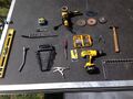
Figure 1- Tools used during construction of RIPSAW
-
Figure 2- Milwaukee Band saw used in construction of RIPSAW
-
Figure 3- Mueller MIG Welder used in construction of RIPSAW
-
Figure 4- Mueller Plasma Cutter used for construction of RIPSAW
-
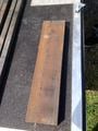
Figure 5- C-Channel iron used for C-bracket
-
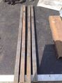
Figure 6- Square iron tubing used for C-bracket
-
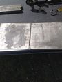
Figure 7- Iron plate used for C-bracket platform
-
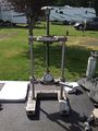
Figure 8- McElroy Compact Chain Sidewinder used for RIPSAW
-
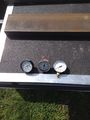
Figure 9- Interchangeable gauges for Sidewinder
-
Figure 10- Polyethylene pipe used in RIPSAW


Cost
The bridge tester items, purchase size, quantity of items, team cost, individual retail cost and total cost of the final design bridge tester are summarized below in Table 1, Table 2, and Table 3.
| Bridge Tester Item | Purchase Size | Quantity | Team Cost | Individual Retail Cost |
|---|---|---|---|---|
| McElroy Sidewinder | (10.25inx12.5inx21.4in) | 1 | Donated | $1,583.00 |
| Iron Plate | (12inx12in) | 2 | Donated | $145.90 |
| Cart with Wheels | (24inx18inx42in) | 1 | Donated | $106.99 |
| Square Tubing | (48inx1.5inx1.5) | 4 | Donated | $34.24 |
| Rectangle Tubing | (72inx1.5inx0.75in) | 1 | Donated | $20.94 |
| C-Channel | (25inx6inx2in) | 1 | Donated | $20.50 |
| Black Spray Paint | 12 oz. | 1 | $8.49 | $8.49 |
| Matte Clear Coat | 12 oz. | 2 | $4.99 | $4.99 |
| Bolts | (3/8inx3in) | 2 | $0.85 | $0.85 |
| Nuts | (3/8in) | 2 | $0.23 | $0.23 |
| Washers | (3/8in) | 6 | $0.23 | $0.23 |
Total Team Cost of Bridge Tester:$22.01
Total Retail Cost of Bridge Tester:$2,182.50
| Bridge Materials | Purchase Size | Quantity | Team Cost | Individual Retail Cost |
|---|---|---|---|---|
| Popsicle Sticks | 1000 Pack | 2 | $5.99 | $5.99 |
| Popsicle Sticks | 100 Pack | 1 | $3.49 | $3.49 |
| Dowels | 8 Pack | 5 | $2.99 | $2.99 |
| Wood Glue | 4 oz. | 4 | $2.49 | $2.49 |
| Fine Sand Block | (4.8inx2.9inx1in) | 1 | $2.15 | $2.15 |
| Bass Wood | (36inx3inx1/16in) | 8 | $1.79 | $1.79 |
Total Team Cost of Bridge Materials:$56.85
Total Retail Cost of Bridge Materials:$56.85
| Task | Hours |
|---|---|
| Dust Equipment | 0.083 |
| Lube Wheels | 0.330 |
| Clear Coat Protection | 1.000 |
| New Black Spray paint coat | 1.500 |
Total Task Hours: 2.913
Testing Results
To test the final design created, each team member made several types of bridges. These bridges were made with the same equipment and materials that would be available to the students that will be making bridges to be tested. Different variations of bridges were constructed to test the flexibility of bridge design the machine could effectively test.RIPSAW was able to successfully test and break each of the bridge type while giving accurate information about how much pressure each one of them could take. All of these tests gave us a good inclination that the machine operated the way it is supposed to.
How to build
Discussion and next steps
Several obstacles arose during the development process of our design that impacted the final design. Many changes to the design occurred to accommodate the various criteria and constraints.
The solution of “Project RamRod,” which scored the highest on the Delphi matrix, had a lot of components that were going to be donated. An integral part of the design is the pump that supplies pressure to the ram. This pump is powered by Alternating Current which allows it to be plugged directly into the wall socket. This specific pump that was supposed to be donated was no longer available. This meant that we would have to buy a pump and this did not meet our cost constraint for the project.
Different alternatives to using the pump were considered, one of which would include an air compressor that that would serve the same purpose. While the air compressor would serve the same function as the pump, it created more obstacles to overcome. The air compressor that could be used was powered by direct current. This meant that in addition to replacing the parts from the compressor that needed it, e.g. the connecting hoses, more parts would have to be located and purchased in order to achieve the constraint of durability. A tickle charger would have to be applied to the power source, a battery, to increase the lifespan of the battery. Another solution researched was to purchase an inverter. An inverter converts Direct Current to Alternating Current. Once again this solution created problems with achieving the cost constraint.
While gathering materials for the project, Rick White, Gas Operations Manager with PGE, had a piece of equipment that is no longer in operation and donated it to the project to be repurposed. This job specific piece of equipment would in fact take the place of several different components of the design. By using the McElroy Sidewinder, the need for a power supply source, pressure gauge, ram, and pump would no longer be necessary. All of the electrical components to the design would be obsolete. The acquisition of the mechanism would have the biggest impact on the specifications of the final design.
References
See Help:Footnotes for more. Template:Reflist