
Dylan Mercier[edit | edit source]
I am Dylan Mercier, a mechanical engineering student at Michigan Technological University. I am currently an intern for Wes-Tech Automation Solutions in the Chicago area and am part of the Open Source Hardware Enterprise at MTU.
Email: dcmercie@mtu.edu
https://www.linkedin.com/in/dylan-mercier-508b7b171/
Interests[edit | edit source]
| Electronics | Cars | Automation | CAD |
Experience[edit | edit source]
- I have built a printrbot simple metal, a DIY 3D printer that is low cost with a medium build plate that is fully upgradeable.
- Worked on multiple large assemblies in Solidworks, Inventor, Autocad and NX
- I have been an intern at an automation company called Wes-Tech Automation Solutions where we design and build automated assembly lines and machines for larger companies.
Enterprise[edit | edit source]
Semester 1 Fall 2019
Recyclebot Industrial v2:
Starting the fall of 2019, our team, consisting of Matt Lekity, Garrick Ensminger, Colton Nelson and Nicki Gallup started a new revision of the current Industrial Recyclebot. The scope of the project was aimed to make it more user friendly, easier to build, and cheaper to source parts. My task as the mechanical design lead was to redesign the machine to incorporate the new ideas and parts that were going to be implemented. The first revision to the machine that is expected to be completed by the start of spring 2020 is the extruder and hopper assembly. The previous iteration had many flaws in this design, where the PLA granules started melting inside the hopper which caused the machine to jam. This problem meant it had to be taken apart and be cleaned multiple times before it can be used again. This was fixed by lengthening the pipe between the extruder nozzle and the hopper by 4-6 inches, which prevents the heat from the heating elements from creeping to the hopper through the pipe. Because this assembly needed to be revised, the entire hopper sub-assembly needed to be changed as well. One of the goals of this project is to make it simple for anyone to build with simple hand tools or common electrical tools. This means that the hopper design needs to be changed as most DIY enthusiasts will not have access to the tools needed to recreate the original design. This meant that the hopper assembly needed to be changed to be made of mostly 3D printed parts, making this sub-assembly easily replaceable and cost effective. These parts were designed to be bolted together, making cleaning and installation easy. This task of redesigning the hot end of the machine is the most involving in the project, while the electrical team carried out the task of automating the process from start to finish, wile also combining each of the existing control boxes into a single arduino.
Semester 2 Spring 2020
Recyclebot Industrial v2:
Continuing with the Recyclebot Industrial v2 project for the fall of 2019, the team now consits of Matt Lekity, Colton Nelson, and Kyle DeRoche. This semester the goal was to finish the project fully including testing and fully 3D print the robot by the end of the Spring 2020 semester. Due to the Covid-19 pandemic, this was not possible so the goals have been altered to work around this problem. The first half of the semester was spent redesigning the hot end of the assembly, which included redesigning the hopper as it was difficult to reproduce without specialty equipment. Because of this, the hopper was designed to be 3D printed as the previous hopper design costed half of our total estimated cost of the robot. This hot end was also redesigned to accept a stepper motor in place of the large DC motor that was driving the robot before as the DC motor was unable to be controlled or slowed down. This caused me to create new parts that will allow the stepper motor to be used, all of which can be 3D printed using PETG filament. After the hot end was designed, the parts were printed and assembled onto the base board using hardware that was bought or supplied in the lab. This hot end is completely ready for testing for when instruction resumes in the Fall. The second half of the semester was spent finishing the CAD assembly of the rest of the robot. Due to the pandemic currently happening, we were unable to physically finish printing and building the robot, so my focus was shifted to completing the entire robot so that it can be printed right away in the Fall of 2020, and be ready for testing immediately. The rest of the redesign consisted of the completion of the cold end, where the vertical tensioners were redesigned to allow more advisability for the user, allowing them to be raised, lowered, and shifted around on the board. Safety covers were also made to prevent injuries due to the hot and moving parts in this robot. These covers were placed over parts that can pinch, burn or cut the user, as safety is the priority in this project due to the amount of heat that is being outputted by the heaters. Each part was also prepped for printing, so that the team next semester can print the parts right away and start building the robot and testing it. The final part of my semester was spent creating a final bill of materials (BOM) that contains ever part needed to recreate the assembly, including screws, bearings, nuts, etc. Documentation was also created to direct the team next semester to where different parts are located and where everything can be found.


Semester 3 Fall 2020
Recyclebot Industrial v2:
Throughout the fall of 2020 semester, the Industrial Recyclebot has been fully designed and built. Previously the hot end of the robot was built and bolted into place, and this semester the cold end design was completed and updates have been made to increase safety. These updates to the CAD design include covers that prevent users or objects from touching the motor driven moving components such as the direct pullers and spooling mechanism. These components will pinch fingers, cut fingers, and pull on objects and could cause harm. Because of this, multiple covers were made to eliminate this risk, as the only way to access these components is to remove the covers. A cover was also made for the hot end of the robot to prevent burning of hands, arms, hair, or foreign objects. Because the hot end of the Recyclebot achieves very high temperatures, a cover was designed (but not printed due to printing limitations) to prevent the barrel or heating elements from being touched. The second cad update has been a slight modification to the layout of the assembly. In order to reduce prototyping costs, previous materials were reused, meaning that the base board that each component is bolted to has also been reused. Because of this, the layout of the robot has been adjusted and can be seen in the picture below. The flow of the design stays the same, but possesses a much smaller footprint.
After the Recyclebot was designed, the components for the cold end were printed and assembled on the board. These components include everything after the barrel of the robot. The Recyclebot is fully capable of running now, and only minor improvements can be made to finish the project. I have also worked with another member of the group to start wiring the electronics to the Arduino controller, which will be used to drive the robot. This wiring has not been completed and will be finished the following semester. The picture below shows the built robot excluding the cover over the barrel of the hot end, and does not include the control box completed due to the incomplete wiring. The mechanical design portion of the Recyclebot is 100% functional, and 98% completed as there are accessory components that can be added to increase the safety and visual design of the robot.

Semester 4 Spring 2021
This semester I started my senior capstone project, the open source cinematography quadcopter. I was the project lead, where I was tasked with creating and managing a budget spreadsheet, ordering parts and components, and designing the quadcopter. Before starting my design work, I researched different methods to build the quadcopter, and found the MultiWii program. This program allows an Arduino Uno R3 to be utilized to fly the drone. Using this program, I determined the proper components that would be needed to build the quadcopter. I determined that the motors would need to be overpowered in order to carry an additional payload in the future and chose the Emax MT2213-935KV motors. These motors are 935kV motors which are paired with 30A ESCs and a 3S LiPo battery. This combination allows the quadcopter to carry a payload almost double its weight without struggling due to the lack of lift. Once these key components were determined, the size of the quadcopter needed to be determined. Because of the possible additional payload in the future, a smaller quadcopter would not generate enough lift, so I determined that a 10" frame was appropriate for this use case. Because the goal of this project is to create a cinematography drone, the RunCam Hybrid Micro FPV camera was used to capture these photos and videos due to its 4K resolution and onboard microSD card.
Working closely with the other members of the team, I designed a frame capable of the 10" propellers, motors, and other components, ensuring that each component would fit properly onto the frame. Each of these components were created with weather resistance in mind, as the quadcopter could encounter unpredicted conditions during flight. Because of this, a cover was developed in order to protect the essential components. Each component was created using FreeCAD and additional open source plugins, specifically A2Plus and FEM. A2Plus handles the assembly portion of the design work, where each part was added to an assembly to confirm alignment with other parts. Once these parts were designed, I proceeded to start printing each part using PETG filament to prepare for assembly next semester.
Cinematography Quadcopter Parts
-
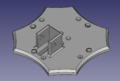
Fig 1: Bottom plate with adjustable camera mount
-

Fig 2: Top plate with mount for Arduino Uno R3
-
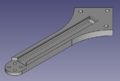
Fig 3: Rear Arms
-
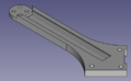
Fig 4: Front left arm
-
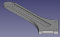
Fig 5: Front right arm
-
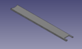
Fig 6: Sliding covers for the arms
-
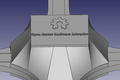
Fig 7: Center cover to keep essential electronics protected
-
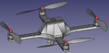
Fig 8: Finished assembly of the quadcopter
-
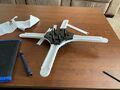
Fig 9: Partially printed frame


The weekends of the semester were spent creating the wiring harness and testing the code. As a team, we were able to successfully gain an output from the IMU giving us values for our pitch, roll, and yaw while bench testing. Due to the nature of troubleshooting, extended delivery times due to covid, and shortage of components, the wiring harness was not finished completely, but the correct wiring diagram was determined for continuation next semester. It was also determined while assembling the wiring harness, that multiple components were lacking some of the features that were necessary in the MultiWii code that was being used. Because of this, multiple components needed to be ordered before the wiring harness was able to be completed.
Fall 2021 Senior Design Paper[edit | edit source]
Executive Summary
The Open Source Hardware Enterprise is a team of engineers, working to expand the open-source community by providing and building upon new or existing platforms. These platforms are entirely community built, tested, and driven, allowing any user to recreate the project or tailor it to their own needs. An open-source quadcopter was developed by the Open Source Hardware team to allow hobbyists and researchers to attach various equipment to it to capture any kind of data. To do this, the quadcopter was created utilizing open-source software, tools, and hardware to create a platform that can be used and modified by anyone. To show the expandability of the quadcopter, a 4K First Person View (FPV) camera, the RunCam Hybrid Micro, is being used as a payload to demonstrate its capabilities as a cinematography quadcopter.
The frame of the quadcopter was designed with a large, flat surface area on the bottom, combined with a high-resolution camera allowing the user to capture high quality photos and videos while attaching additional equipment, sensors, and payloads for various tasks. The design of the quadcopter combined with the components and materials chosen, allows it to be easily modified, while retaining its strength during flight and impact. A 3D computer aided design (CAD) model was created using FreeCAD, an open-source CAD software. This software allowed the team to create the frame and test it using Finite Element Analysis (FEA) to ensure it was able to withstand the load of the quadcopter under operation. The FEA results yielded low stress and displacement values under maximum thrust and impact, with various components designed to fail under impact loads to reduce the damage to the main frame components. This frame design was then manufactured using 3D printing technology, using Polyethylene terephthalate glycol (PETG) to retain its strength, while reducing the weight of the frame, allowing for addition payloads to be carried. To carry the payload, the Emax MT2213-935KV motors will be used, combined with 10” propellers. This motor and propeller combination allows the quadcopter to carry heavy payloads and be agile during flight.
The open-source software, MultiWii, is used to control the quadcopter, giving the user the ability to modify every part of the code. Because MultiWii is an open-source project, its features and accessibility are constantly expanding with a large support base from the community, making it an excellent choice as a flight controller. This software runs off an Arduino microcontroller, making every portion of the quadcopter open source besides the standard essential quadcopter components. Utilizing open-source flight controller software allows implementation of devices normally not found on quadcopters, allowing its use by researchers to gather sensitive data from a remote location. MultiWii offers an extensive library of features and an enhanced GUI allowing testing to be done prior to initial flight to ensure that each component will work properly. Preliminary testing of both the motors inputs and responses as well as the Internal Measuring Unit (IMU) were done through the MultiWii GUI prior to connecting the components to a power source to test the balance, responsiveness, syncing of the quadcopter during flight.
Acknowledgements
The cinematography quadcopter team would like to extend its gratitude to the rest of the Open-Source Hardware Enterprise (OSHE) team for their support with this project, as without the team’s input, various elements of the project would not have been reconsidered, weakening the design of the quadcopter. The team would also like to thank Dr. Shane Oberloier for assistance with understanding complex electrical circuits and Arduino coding, and Rick Berkey for his support and guidance throughout the project, offering insight as to how to improve the design. Their support and guidance allow the team to continuously improve their skills and knowledge, leading to more innovative and effective solutions. I would also like to thank Harris Neill for his help during the first semester understanding the MultiWii code, and Joaquin Ganoza for his help during the building and testing phase of the project, helping me troubleshoot various problems that arose during the project.
Introduction
The basis of a quadcopter is to allow data to be collected from an aerial point of view. This data can be anything from pictures, air density, temperatures, or other forms of data from additional sensors. The most common use of a quadcopter is for cinematography, as many users attach a camera to capture high-resolution photos and videos. Due to the design limitations of many quadcopters on the market, additional accessories are rarely added to existing quadcopters, leading users to either build a new design or buy another frame for each device. The opportunity exists for a design that can be adapted to each user’s requirements by being semi-modular or having the ability to mount multiple different components to the frame with minimal complexity. Creating such a design would be to create an open-source platform for users to consistently expand and support new an innovative ideas and solutions.
Objectives and Constraints
Objectives
The goal for this project is to design and manufacture an open-source quadcopter that is designed around the expandability by any user. This means that the design should be easy to manufacture for anyone with basic open-source tools, and should be easy to operate and set up, while having the ability to be adapted to any needs the user has (additional payload, visual changes, performance changes, etc.). To do this, the goals of the project are as follows:
· Open-Source frame design
o FreeCAD will be used allowing anyone with access to a computer to make changes and use the design.
· Open-Source code controlling the quadcopter
o Open-source project (MultiWii) will be used as a foundation to control the quadcopter.
· Water-Resistant design
· 4K video capture
o Integrating a common 4K quadcopter camera to be used through the Arduino coding to capture up to 4K photos and video.
§ Photos and videos will be saved to the onboard micro-SD card inside the Arduino.
· Open-Source controller hardware.
o Eliminates the proprietary microcontroller found in every quadcopter on the market.
o Allows the community to use different styles of Arduino controllers to add functionality or reduce weight for purposes such as racing.
· 3D printed frame
o Allows changes to the frame to be printed easily and quickly reducing the manufacturing time.
· Perform basic quadcopter flight maneuvers
o Ability to be controlled from a handheld transmitter.
o Take off and land safely.
o Precise and accurate controls.
Constraints
Due to the nature of the project, many users will not have access to proprietary/specialty software and tools. This limited accessibility leads the user to seek out other means of design and operation. Other concerns such as strength and durability need to be considered as damage to the quadcopter can be dangerous to both the components, pilot and bystanders. To address these concerns, multiple limitations are placed on the project to make it accessible to everyone:
· Open-source software will be used to design and develop the frame and electronics
o FreeCAD (Open-source CAD software) will be used to design the 3D model of the frame
o MultiWii Arduino software will be used to generate the code required to fly the quadcopter
· Open-source tools will be used to manufacture the frame of the quadcopter
o 3D printing will be the basis of manufacturing for this project, as it allows almost any user to manufacture the frame of the quadcopter
· Must be able to withstand forces both during flight and during an uncontrolled landing
· Every component needs to be covered and the quadcopter needs to be water-resistant in the event of inclement conditions during flight or landing
· Reduce cost to under $550 for final product minus testing equipment.
· Complete the project within a 2-semester time frame.
· Follow FAA regulations8.
· Thrust to weight ratio of 2.
Project Planning and Timeline
The project’s timeline can be found below in Table 1, where the majority of the design work was the focus during the first 14 weeks, while the remaining duration of the project was focused on the electrical, coding and testing of the quadcopter. This timeline was determined due to the large presence of Covid-19 during the initial 14 weeks of the project, while the second 14 weeks allowed the team to shift focus back to the lab to continue testing and analysis of the quadcopter. This timeline was followed with minor changes being made to the second semester, as unforeseen problems during the coding and testing phase utilized more time than initially intended.
Table 1: Cinematography quadcopter weekly project timeline.
| Week | Milestone (Spring 2021) |
| Week 1 | Begin semester / Initial contact with advisor |
| Week 2 | Draft project plan and submit approval request |
| Week 4 | Finish BOM item selection and have parts on order |
| Begin design of the quadcopter frame | |
| Week 8 | Finish design of quadcopter frame |
| Begin coding Arduino and adapting selected parts | |
| Week 9 | FEA analysis on the quadcopter frame |
| Begin printing quadcopter frame | |
| Week 10 | Test fit printed parts and make adjustments |
| Exam week | Enterprise Review |
| Week | Milestone (Fall 2021) |
| Week 1 | Begin semester |
| Week 2 | Finish code for the Arduino |
| Week 3 | Begin testing code |
| Week 4 | Make revision in code |
| Week 5 | First test flight |
| Week 6 | Achieve stable hover and control while flying |
| Week 7 | Generating video and photo from the onboard camera |
| Week 10 | Begin documentation |
| Week 14 | Final documentation and presentation |
Project Budget
The estimated cost can be seen in Table 2 below. This budget is divided into multiple different categories, as some components were used strictly for testing and were not used in the final design of the quadcopter. Because of this, the total cost for the quadcopter can be reduced by eliminating these parts. Other components that were used may or may not be available due to the rapid growth in the quadcopter community, as certain components are often replaced quickly with updated versions. An example of one of these components would be the IMU, but a replacement for this component can be easily sourced if it has the same degrees of freedom as the one that is currently being used. Many of these parts can be sourced directly from the manufacturer’s website/store, while most of them were sourced from a third-party source. As seen in Table 2, the team was able to undercut the budget of $550 by $30.37 including the testing equipment (goal was to keep the budget below $550 without testing equipment).
Table 2: Cinematography quadcopter itemize project budget.
| Item | Quantity | Estimated Price | Spent |
| Components | 370 | ||
| Battery | 1 | $17.09 | |
| ESCs | 4 | $59.92 | |
| Brushless Motors | 4 | $61.36 | |
| Arduino Uno R3 | 1 | $23 | |
| 4k Camera | 1 | $90.97 | |
| 1045 Propellers | 1 package | $11.99 | |
| Flysky receiver | 1 | $17.37 | |
| FrSky Receiver and Transmitter Combo | 1 | $58.59 | |
| Arduino Uno R3 Prototype PCB | 1 package | $18.99 | |
| Hardware | $150 | ||
| M4 socket head cap screws | 1 package (12 used) | $7.81 | |
| Tapered Heat set inserts | 1 packager (12 used) | $6.58 | |
| 1N4001 Diodes | 1 | $2.03 | |
| 40 pin snap headers | 2 | $1.94 | |
| Bullet Connectors | 1 package | $7.99 | |
| 12awg Wire | 1 package | $9.36 | |
| 18awg Wire | 1 package | $6.98 | |
| PETG Filament | 2 rolls | $63.98 | |
| Testing Equipment | 30 | ||
| Battery Voltage Meter | 1 | $7.23 | |
| Power Distribution Blocks | 2 | $11.08 | |
| Power Distribution Block Jumpers | 2 | $6.04 | |
| Total | $550 | $519.63 |
Concept Design/Selection
System Processes
To determine the optimal parameters for the quadcopter, the system must be analyzed as a whole to determine the processes it will experience. Figure 1 below shows a block diagram of the quadcopter system, showing how each input and component is linked to one another. This diagram also shows how the process is calculated from the user inputs, to produce thrust as an output for the system. The user starts by giving input using the transmitter, which is linked to the receiver in the quadcopter. This receiver translates the input the user gave and sends the input to the Arduino. Combined with the user input, the IMU calculates the quadcopter’s position in space to determine if automated inputs are necessary to keep the system stable, while the battery supplies power to various components. After the inputs are calculated by the Arduino and MultiWii software, it sends an output to the four motors and ESCs to produce the correct amount of thrust. This thrust can vary for each motor, as one motor may produce more thrust than the other three to tilt or turn the quadcopter in a certain direction. The user can also specify whether a video is to be recorded or not, where this command is sent to the Arduino, redirecting it to the camera’s module, starting or stopping a video and saving it to the onboard SD card.

Figure 1: Quadcopter System Block Diagram.
Determining the optimal frame size and shape
For a quadcopter to be designed, there are various factors that need to be addressed before the design process can begin. The first factor is the size of the quadcopter, as there are various sizes ranging from 4” quadcopters all the way to sizes greater than 12” quadcopters. Due to the requirements of this project and the necessity to carry an additional payload, a larger size quadcopter is required as it will produce more thrust to lift the additional payload. Because we are using the Emax MT2213 935KV motors, the manufacturer provides a chart for the maximum thrust each motor can produce depending on the size of the propeller, which is either an 8” or 10” propeller. These calculations can be seen below in Figure 2, where a 1045 propeller was used in this project due to the larger maximum thrust. These motors were chosen as they provided a large amount of power when paired with a 30A ESC as seen in Appendix 1 and Figure 2. The motors need to be powerful for this quadcopter in order to carry any additional payload the user mounts to it, and 935kV motors satisfy this requirement.

Figure 2: Motor thrust manufacturer data.
Looking at this chart, there are multiple different thrust values for a 1045 propeller. In order to determine the maximum value, the largest current is used to simulate the motors at full throttle, yielding a maximum thrust of 670g per motor. Because this is a quadcopter using 4 motors, the total thrust that the quadcopter can produce is 2,680g, which is double the combined weight of the frame, components, and payload. This value was used as one of the design criteria, as the total weight of the quadcopter and components needs to be less than this value to ensure that an additional payload can be carried, as the thrust to weight ratio needs to be greater than one based on the equation below2. The optimal value for the thrust to weight ratio is 2, as this value allows the quadcopter to hover at half throttle. This means that the quadcopter will be able to accelerate out of a hover to gain or lose altitude, as a thrust to weight ratio lower than 2 will limit the acceleration and possibly deny any gain in altitude.
Propeller clearances
Because we are using a 1045 propeller, seen in Figure 3, the frame must be able to accommodate a 10” diameter at the end of each arm without interference with the other components. This is crucial as any interference will cause damage to both the frame and the components mounted on it. To adhere to all requirements of this project, the propellers will have a tight interference with the center body of the quadcopter, which will further reduce the overall size and weight, allowing for a heavier payload to be carried. Due to the motors being hard mounted to the frame, this tight tolerance can be held as the motors will not shift or torque during full throttle maneuvers.

Figure 3: 1045 propeller critical diameter dimension. The shape of the frame design will also play a role in the clearances of the propellers. If the frame is too small, the propellers will interfere with each other during operation. Because of this, a minimum spacing of 10” between the rotational axis of the propellers and motors needs to be held, while a larger spacing is necessary to house the Arduino and additional components in the center of the quadcopter. Based on the research found in the References and Research Findings at the end of this report, it was determined that a square-cross shape frame design was ideal as it maximized the space in the center of the quadcopter and eliminated the need for additional stability components. The structural stability found using a square-cross shaped frame design is also much greater than a hybrid-X shaped quadcopter where the quadcopter’s footprint is rectangular in shape compared to square in the case of a square-cross shaped frame design1-3,5,7.

Figure 4: Square-Cross quadcopter frame (left) compared to Hybrid-X quadcopter frame (right)
Protection
The quadcopter must also be water-resistant as per the requirements stated previously. To do this, the Arduino, receiver, IMU, ESCs and camera board will be housed under a cover in the center of the quadcopter. This allows the quadcopter to be protected when it comes in contact with water from either landing or flying through different weather conditions. This cover will be slightly conical in order to provide the tight clearances with the propellers during flight.
The final protection design choice for this quadcopter is to raise the frame off the ground. This is done through feet mounted below the motors. These feet will allow the user to take off when the ground is wet or covered in debris without risk of damaging the components attached to the quadcopter. These feet also provide another purpose as they allow space between the bottom of the frame and the ground for mounting different equipment and payloads. In this project, the camera is mounted on the bottom of the quadcopter and is suspended above the ground due to the implementation of these feet on each corner. Because some payloads will be larger than others, the size of these feet will need to be easily changed by the user to adapt to different scenarios and purposes. The feet also provide a secondary purpose as they absorb much of the shock and force that is experienced form landing. The feet must be able to bend slightly during landing to reduce the displacement in the arms and prevent failure in other components of the frame.
Control
The quadcopter will be controlled using an Arduino Uno R3 using the open-source software MultiWii. This software can be used to control any aerial machine and is built specifically to reduce the complexity for the user. This software is open source and is built by the community and is constantly expanded to include new components and features, which will allow future users to easily add different equipment as payloads. In this project, the payload of a camera is added as an auxiliary input in the code and can be controlled using the handheld transmitter to record photos and video.
Detailed Design and Analysis
Combining the initial design selection and the requirements described previously, the team has determined the optimal design for the quadcopter. The frame of the quadcopter consists of 4 arms that are almost identical aside from a rectangular cut made in 2 of the arms to allow the camera board to pass through. Each arm has been hollowed out to allow the motor and Electronic Speed Controller (ESC) wires to be routed through them with the optional cover to be placed on top to increase the water resistance if flying in conditions that warrant it. Four mounting locations are present in each arm to allow M4 bolts to pass through them as an interference fit to reduce lateral movement and vibrations from the motors while flying.

Figure 5: Arm of the quadcopter frame showing the rectangular cutout present in 2 of the 4 arms to allow the camera board to pass through the frame. After the arms were designed, FEA was completed using FreeCAD’s FEA module FEM. FEM allows the part to be imported, meshed, and have forces and fixed constraints placed on various components of the part. For the arm, a mesh was applied to the body using the NMesh tool, with a maximum mesh size of 1000. Utilizing a mesh size that is too small will increase calculation time by the FEA software being used, often so much so that a result is never obtained due to the large number of nodes, while a mesh size that is too large will result in data that is not fully correct. A larger mesh size takes less time to compute due to the smaller number of nodes being analyzed. Using the NMesh tool, the maximum mesh size allows for a coarser mesh in areas with less complex geometry, while allowing a finer mesh to be applied to areas with more complex geometry. This allows areas such as the flat top surface to be calculated quicker due to the lower chance of stress concentrations, while areas such as the end of the arms with more stress concentrations are given the minimum condition, allowing a smaller mesh with more nodes to be applied to it. Constraints were placed at each hole location as well as the back edges of the part to simulate it being fixed between the top and bottom plate. After the constraints were placed, a force on the face at the end of the arm where the motor mounts (right) was placed with a magnitude of 15N, which is roughly the force the arms will experience during full throttle.

Figure 6: Displacement FEA results for the arms of the frame using FreeCAD’s FEM module yielding a maximum displacement of 3.4mm and an average displacement of 1.53mm.
From the FEA results using FreeCAD’s FEM module, it was determined that the absolute displacement of the arm was located on the end of the arm where the motor is mounted, with a maximum displacement of 3.4mm, and an average displacement of 1.53mm. This displacement will only be experienced for a very short amount of time, as once the quadcopter takes off, the rest of the frame begins to move with the motors, lowering the displacement significantly. Similarly, the Von Misses stress can be calculated using the FEM module, resulting in a maximum stress of 9611.4 kPa. When comparing this maximum stress to the tensile strength of PETG (the material the frame is made of), the tensile strength of PETG is 53 MPa.
Using the equation above, the factor of safety can be determined for the arm by dividing the ultimate tensile strength (53 MPa) by the found maximum Von Misses stress. This results in a factor of safety of 5.51. A factor of safety of 1 is the minimum required factor of safety, while a factor of safety of 2 is desired, meaning that the arms are strong enough to withstand the forces of maximum throttle flight.

Figure 7: Von Misses FEA results for the arms of the frame using FreeCAD’s FEM module yielding a maximum Von Misses stress of 9611.4 kPa. The remaining portion of the frame is made up of 2 plates and a cover. The bottom plate seen in Figure 8 houses the camera module with open space to add mounting points for additional modules. This bottom plate is held on using countersunk M4 screws which are passed through the arms, screwing into heat set inserts molded inside the top plate. To mount the camera onto the quadcopter, a protective box was created with 3 sets of mounting holes. This box will protect the camera in case of a crash landing in the event that the feet break away from the frame of the quadcopter. The multiple sets of mounting holes allow the camera to be angled downward at either a 45-degree or 90-degree angle. This lets the user record photos or video from an aerial point of view instead of straight on.

Figure 8: Bottom plate with variable position camera mount and countersunk mounting holes. The top plate has heat set inserts molded into it for each arm and has 4 standoff posts for bolting down the Arduino. The Arduino has been raised above the surface of the top plate to allow wires, IMU, ESCs, and receiver to be mounted below it. Figure 9 shows the top plate with all the components placed on it in their initial locations, while the final location of the receiver is located on top of the Arduino. The components placed below the Arduino are mounted to the top plate using double sided insulated tape. This insulated tape provides a barrier between the components and the molded heat set inserts to prevent shorting from happening. Using insulated tape also allows prevents the components from being hard mounted, as in the event of an in-flight failure or an uncontrolled landing, hard mounted components could snap at their mounting points.

Figure 9: Top plate with Arduino (1), Camera Board (2), Receiver (3), IMU (4), and heat set inserts mounted. The next part of the frame that was created was the cover. This cover houses everything on the top plate and is held to the rest of the frame using 4 heat set inserts and 4 M4 screws. The sides of the cover are angled along a specific path to allow the propellers to spin freely without hitting the cover. This angle was determined using the FEA results from the arms, giving a minimum of a 4mm gap between the tips of the propellers and the cover to compensate for the maximum displacement of the arms, as well as any flex the propellers may experience.

Figure 10: Angled cover to protect internal components and prevent propellers from interfering with the frame. The final part of the frame that was designed was the feet. These feet utilize the mounting locations of the motors, as the 4 bolts used to secure the motors are also used to secure the feet to the frame. These feet were designed with the intention to break before any other component as they are small and easy to replace. The feet were designed with a conical shape to provide rigidity with a slight outward bend to them to allow them to flex. These can be seen below in Figure 11.

Figure 11: Cinematography Quadcopter feet. Using the same FEM module as the arms, FEA was conducted on the feet to simulate a landing from 1m in the air. This impact testing was done by placing constraints on the top of the feet where they meet the underside of the arms, and a force was placed on the bottom of the feet. This test yielded a maximum displacement of 1.63mm and an average displacement of 35 micrometers. Because of the outward bend to the feet, this 1.63mm can be absorbed by the feet without failure.

Figure 12: Absolute displacement (left) and Von Misses stress (right) for the quadcopter’s feet.
Calculating for the Von Misses stress on the feet yielded the maximum stress on the entire frame, with a maximum stress of 31.59 MPa. Though these feet yielded a large Von Misses stress, the results are still below the tensile strength of 53 MPa. Like the arms, the FOS for the feet can be determined using the same equation, yielding a FOS of 1.68, which is above the minimum requirement.
Combining each of these parts, the frame was assembled using the previously described M4 screws and heat set inserts. The motors, propellers, Arduino, and the rest of the components can then be added as seen in Figure 13 below. The weight of the frame without any additional components was determined to be 411g, while the weight of the frame with components was determined to be 1088g. Because the total thrust of the quadcopter is required to be double the total weight, the quadcopter is able to safely fly and perform a vertical takeoff and landing safely.

Figure 13: Completed assembly of the quadcopter with all components mounted including the optional arm covers.
Fabrication/Manufacturing
Once the frame of the quadcopter is designed using computer aided design (CAD), the files can be exported to a common format (STL or STEP) and 3D printed. 3D printing was the chosen manufacturing method as it is a common open-source option that many hobbyists have access to. 3D printing also allows the user to print the changes they make easily and quickly with minimal hassle. There are 3 common types of filaments used in 3D printers, Polyethylene terephthalate glycol (PETG), Acrylonitrile butadiene styrene (ABS) and Polylactic acid (PLA). PLA has the lowest strength of the three options and typically shatters upon impact, while ABS is stronger and tends to bend instead of break during impact, making it a more ideal choice for a quadcopter frame. The last option is PETG, which is stronger than ABS when it is printed using layer lines like how a 3D printer works6. Given that the frame should not flex and should remain rigid, the optimal choice is PETG due to its superior strength and rigidity. The properties for PETG can also be found in Appendix E.

Figure 14: PLA vs ABS vs PETG material properties8. Before a part can be printed, it needs to be “sliced”, meaning that the part needs to be broken down into individual layers that it will be printed in. A 3D printer works by melting the chosen material into a thin strand, creating the part in many different layers. Once a full layer is printed, the 3D printer will move its nozzle upwards in order to start printing the next layer. When slicing the parts before printing, there are multiple factors that can affect the print speed, resolution, and strength of a part. The first setting that was adjusted was the quality of the print. A higher resolution will reduce the visibility of individual layers, but takes much longer to print, so a standard to high resolution was used for most parts. The second setting that was adjusted was the infill of the part. 3D printed parts are not solid, and are often partially hollow, filled with a certain pattern, in this case a triangular grid pattern. This was chosen as it increases the strength of the part when compared to a rectangular infill pattern, and the infill was set high to retain strength throughout the part, but reducing the overall weight, allowing for larger payloads to be carried. The final setting that was added was the use of support. Support allows for portions of the part to have overhangs or internal cavities that could not normally be done using traditional manufacturing methods. An example of this is the use of supports on the cover, where the mounting tabs create a negative cavity that cannot be made on any other machine. For this project, a Lulzbot Taz 3D printer was used as it provides a large build volume, 280mm x 280mm x 250mm, and provides good quality. Because a Lulzbot 3D printer is used, the Lulzbot version of Cura is being used as a slicer, which will import the STL files created from the 3D models, and slice the parts into individual layers, applying the chosen settings in Cura.

Figure 15: Cura slicer used to print each part using PETG and triangular infill. Once the parts are printed, excess support material can be removed, and the parts can be assembled. Figure 16 below shows the assembled parts without the motors, props, or electrical components assembled on the frame. The heat set inserts are inserted into the top plate and cover to allow the M4 screws to secure each part together, and the holes in the arms are undersized to create an interference fit to prevent lateral movement and vibrations during flight. This figure was taken during testing where the propellers are not attached to the motors for safety, and the center cover and feet are removed to make handling the electronics easier.

Figure 16: Assembled 3D printed frame with components excluding center cover, feet, and propellers during testing.
Coding and Electrical
After 3D printing and building the frame, each component can be attached and wired to the Arduino. Figure 17 below shows the wiring diagram for this quadcopter, where each motor runs to an ESC, which uses a Pulse Width Modulation (PWM) input on the Arduino to be controlled. A PWM input was chosen for many reasons, the first being its efficiency. A PWM signal will have a much smaller voltage drop when compared to a direct analog signal. This allows the motors to have an accurate voltage applied to them, allowing them to be used to their full potential. The second reason is that the signal remains digital throughout the entire circuit. A digital signal is important as it allows the motor to be controlled variably as an analog signal sends a simple on/off, while the digital signal allows for greater control. Using a PWM input also eliminated the need for resistors in series which causes further dissipation and decreases efficiency and control.

Figure 17: Cinematography Quadcopter wiring diagram.
With the motors connected to the ESCs, and the ESCs connected to the Arduino, Power and Ground as seen in Figure 17, the receiver can be connected to the Arduino to allow user inputs from the transmitter (handheld controller). This receiver requires a signal for each motor, as well as a power and ground from the 5V and ground pins of the Arduino. A similar series of events is also done for the Inertial Measurement Unit (IMU) to allow the quadcopter to read its position in space relative to each axis. The final component that is added is the camera. The camera is wired using a power and ground from the Arduino, with a signal wire tapped into the shutter button circuit controlled using an analog signal from the Arduino. Since the shutter button only needs activation with no control, an analog signal can be used, leaving further PWM inputs open in the event that an addition piece of equipment needs to be added.
Once the frame is 3D printed, testing can commence to confirm each component works as intended. To do this, the MultiWii software was used to control the Arduino. This software is open-source and allows the user to input various components into the code to utilize the predefined PID parameters. These components are inputted into the code by uncommenting the corresponding line as seen in Figure 18.

Figure 18: Config file in MultiWii allowing users to input components to simplify the coding process.
Once the components are inserted or added to the code (in the case that a component is not listed such as the IMU being used in this project), the code can be uploaded to the Arduino. MultiWii comes preinstalled with a custom graphical user interface (GUI) which allows the Arduino to be plugged into a computer via USB and controlled virtually. This GUI can be seen below in Figure 19, where the IMU statistics can be seen on the left side while the transmitter (handheld remote) inputs can be seen on the right-hand side, represented by thrust, pitch, yaw and roll.

Figure 19: MultiWii main GUI showing the IMU statistics (left) and user inputs (right).
Testing and Validation
Once the initial wiring and code was completed, the quadcopter was tested. The initial testing was conducted without the propellers attached to the motor with the Arduino plugged into a computer to utilize the GUI statistics. Table 3 below show the testing matrix that was used for the initial testing to verify that the quadcopter was able to safely fly.
Table 3: Testing and Validation Matrix (P denotes passed)
| GUI
(ability to see response in GUI) |
Quadcopter
(ability to see/hear physical response on quadcopter) |
User Transmitter
(Ability to see response on the user transmitter) | ||
| Arduino Arms | P | P | ||
| ESCs Arm | P | P | ||
| IMU Response | P | P | ||
| Motor Response | P | P | P | |
| Receiver Response | P | P | P | |
| Camera Response | P | P | ||
Using this testing matrix, each component was tested through various tests relating to a response from the GUI, Quadcopter, and User transmitter. These tests ensure that all 3 inputs can either control or react to an action that happens. During testing, the GUI, quadcopter, and user transmitter were able to properly interact with each other resulting in the quadcopter having the ability to safely take off, hover, respond to various inputs and land. These results can be seen below in the following figures.
Utilizing this GUI, the quadcopter can be flown virtually to test each component. Doing this, the inputs from the transmitter were tested to ensure that the motors were responding properly. This was done by using the built-in serial plotter in the GUI, which converts the digital signal that is represented by numbers into a chart. This chart is seen below in Figure 20, where the response of each control movement is seen through the bars in the top right, while the PID parameters being used are shown in the top left. These PID parameters are determined using baseline values calculated using the MultiWii software, which will automatically adjust the parameters to achieve a stable flight.

Figure 20: Input, motor, and PID testing results using the MultiWii GUI.
From these results, it can be concluded that the PID parameters are sufficient in controlling the quadcopter. While testing these inputs, the motors were connected to the battery to allow them to spin freely without the propellers attached. Adjusting the various inputs on the transmitter yields different responses in the chart. Each bar represents a different input (Throttle, Pitch, Yaw, and Roll), where this testing was done by adjusting each input to a different value to determine if the Arduino can handle multiple inputs at once. From this test, it was concluded that the Arduino Uno is sufficient in controlling the quadcopter, while the MultiWii software can achieve safe and reliable input management.
The second test that was done involved the response of the IMU. The IMU that was chosen is a 9 Degree of Freedom (DoF) IMU which will allow the quadcopter to determine its correct orientation at any moment. To test the responsiveness of the IMU, the MultiWii GUI was used to gather data, as the IMU data can be gathered similar to the input and motor testing. These results can be seen in Figure 21, as the quadcopter was rotated in multiple directions while the motors are connected to the battery.

Figure 21: IMU testing results using the MultiWii GUI.
Like the input and motor testing, the chart at the bottom of Figure 17 shows the response from each DoF as a different color. During this test, no user inputs were given via the transmitter, requiring the motors to adjust using the PID gains to compensate for unexpected angle. From this test, the motors responded by attempting to return the quadcopter to a level position that was parallel with the ground, while the results gathered from the IMU showed accurate readings compared to our movements. As seen in the figure, the accelerometer readings were much larger than the gyroscope readings due to the motors attempting to correct the movements we made to achieve a stable hover.
The final testing that was done was to determine if the camera can be successfully triggered from the transmitter. To do this, the camera was wired according to the wiring diagram seen in Figure 17. One of the auxiliary switches for the camera was used to toggle the shutter button activation, sending either a photo or video to the SD card installed on the standalone camera board module. The goal of this test was to successfully gather a picture of the OSHE lab using the camera while attached to the frame of the quadcopter. The photo gathered from this testing can be seen in Figure 22, showing that the camera is able to be successfully controlled.

Figure 22: Picture obtained using the camera module on the quadcopter.
Conclusions and Future Work
This cinematography quadcopter integrates open-source software and hardware to create a foundation for the open-source community to build upon. This quadcopter utilizes a 3D printed frame using PETG to achieve the desired strength, although the design can be easily printed in other materials based on the needs of the application, while being designed using the open-source CAD software FreeCAD. The use of FreeCAD allows any user to make changes to the frame by changing the design, such as adding mounting locations for additional equipment without the need for specialty software. The frame was designed to achieve the maximum rigidity in the key components such as the arms and base plates, while other components were designed to flex and break under high loads. The arms were designed with a FOS of 5.51, allowing it to withstand large impacts before yielding, while the feet of the quadcopter were designed to take the impact load during landing by flexing. FEA was performed to determine resistance to a drop 1m above the ground, resulting in a FOS of 1.68, being the first component to yield upon impact. Because the frame was designed to be rigid, the main components had minimal displacement under load, while minimizing the weight of the quadcopter, increasing its ability to carry larger payloads.
Standard quadcopter components were utilized with the open source MultiWii software which allows for control over every aspect of the quadcopter. The MultiWii software allows the user to input the specific components being used, and automatically determines the proper PID gains to control the motors. This software also allows the quadcopter to recognize its position in space relative to each axis and make corrects automatically when it experiences unexpected angle. Utilizing this software, the quadcopter can fly safely and reliably with enough power to carry an additional payload.
To continue the design of this quadcopter, additional sensors could be added to increase the quadcopter’s utility. The addition of a LiDAR sensor or altimeter will allow the quadcopter to achieve a stable hover without any user input by referencing either the ground or using GPS positioning to determine its altitude. Another addition to the quadcopter that can be implemented in future work would be the optimization of the frame in order to reduce its overall weight while retaining its strength. This can be done with specialty software such as Altair’s Inspire software which allows the user to import geometry and automatically optimize it. This would allow the quadcopter to become much lighter utilizing unconventional geometry and modeling techniques. Because of the nature of the quadcopter being an open-source project, there are an infinite number of revisions that can be made to improve its design, and the participation by the open-source community will likely implement these ideas and carry the design further.
Further investigation into the fatigue life of the different components of the quadcopter will also determine which components need to be reworked in future iterations. The fatigue life of each component will determine how many take off or full thrust maneuvers can be done before the arms of the quadcopter fail. This required more research and testing of the PETG material to determine where the infinite life range lies and whether the maximum stress applied to the arms under full throttle lies inside this infinite life boundary. Fatigue strength can also be looked at to determine what the maximum stress is before failure at the life cycle of the part, guiding further iterations.
References and Research Findings
1. Bhandari, A., Ahmad, F., Kumar, P., & Patil, P. P. (2019). (tech.). Design and Vibration Characteristics Analysis of Quadcopter Body Frame. International Journal of Applied Engineering Research. Retrieved March 2021, from https://www.ripublication.com/ijaerspl2019/ijaerv14n9spl_13.pdf.
2. Javir, A. V., Pawar, K., Dhudum, S., Patale, N., & Patil, S. (2015). (tech.). Design, Analysis and Fabrication of Quadcopter. Journal of Advance Research in Mechanical and Civil Engineerin. Retrieved March 2021, from https://www.google.com/url?sa=t&rct=j&q=&esrc=s&source=web&cd=&ved=2ahUKEwjexdH8xM30AhXLG80KHVsXD64QFnoECAQQAQ&url=https%3A%2F%2Fnnpub.org%2Findex.php%2FMCE%2Farticle%2Fdownload%2F342%2F304&usg=AOvVaw06khR3MMLkmDOntZsxSDwj.
3. Kuantama, E., Craciun, D., & Tarca, R. (2016). (tech.). QUADCOPTER BODY FRAME MODEL AND ANALYSIS. University of Oradea. Retrieved March 2021, from http://imt.uoradea.ro/auo.fmte/files-2016-v1/Endrowednes%20Kuantama%20-%20Final%20Quadcopter%20Bodyframe%20Model%20and%20Analysis.pdf.
4. Parandha, S. M., & Li, Z. (2018). (tech.). Design and Analysis of 3D Printed Quadrotor Frame. International Advanced Research Journal in Science, Engineering and Technology. Retrieved March 2021, from https://iarjset.com/upload/2018/april-18/IARJSET%2011.pdf.
5. Santiago, J. M., & Kasley, K. L. (2017). (tech.). Design & Development of a 3D-Printed Quadcopter Using A System Engineering Approach in an Electrical Engineering Masters Capstone Course (pp. 1–22). American Society for Engineering Education.
6. Simplify3D Software. (2019, May 30). Properties table. All-In-One 3D Printing Software. Retrieved March 2021, from https://www.simplify3d.com/support/materials-guide/properties-table/.
7. Yemle, S., Durgude, Y., Kondhalkar, G., & Pol, K. (2019). (tech.). Design & Analysis of Multi-Frame for Octo & Quad Copter Drones. International Research Journal of Engineering and Technology (IRJET). Retrieved March 2021, from https://www.irjet.net/archives/V6/i6/IRJET-V6I6596.pdf.
8. Recreational Flyers & Modeler Community-Based Organizations. (2021, September 2). Retrieved December 10, 2021, from https://www.faa.gov/uas/recreational_fliers/.
9. Dielectric Manufacturing. (2021, November 19). Material properties of thermoplastic PETG. Dielectric Manufacturing. Retrieved December 10, 2021, from https://dielectricmfg.com/knowledge-base/petg/.
Appendix
Appendix A: Assembly BOM
| Part Number | Part Name | Quantity | Weight (1 Part) | Part |
| 1 | Top Plate | 1 | 69g | Center Plate Top.FCstd |
| 2 | Bottom Plate | 1 | 71g | Bottom Plate With Camera Mount.FCstd |
| 3 | Front Left Arm | 1 | 42g | Front Left Arm.FCstd |
| 4 | Front Right Arm | 1 | 42g | Front Right Arm.FCstd |
| 5 | Arm | 2 | 43g | Arm.FCstd |
| 6 | Center Cover | 1 | 49g | Cover V3.FCstd |
| 7 | Arm Cover | 4 | 5g | Sliding Cover.FCstd |
| 8 | Feet | 4 | 3g | Feet.FCstd |
Appendix B: Assembly Procedure
This assembly procedure describes the required steps to completely assemble the quadcopter.
1. The table below lists all the required hardware and tools necessary to completely assemble the frame and components of the quadcopter.
| Component | Description | Quantity |
| Fastener | M4 x 0.7 x 25 | 12 |
| Fastener | M2 x 0.4 x 15 | 12 |
| Fastener | M3 x 0.5 x 10 | 4 |
| Heat Set Insert | M4 x 0.7 | 12 |
| Tooling | Description | Quantity |
| Allen Key | M4 | 1 |
| Allen Key | M2 | 1 |
| Allen Key | M3 | 1 |
| Soldering Iron | Typical Soldering Iron | 1 |
| Needle Nose Pliers | Small | 1 |
2. Install the heat set inserts into the top plate of the quadcopter by placing the heat set inserts above the countersunk holes. Note, 4 of the holes are not countersunk, the remaining heat set inserts will be used in step 8 to secure the cover to the rest of the frame. Place the soldering iron inside the heat set insert and apply a small amount of pressure downwards making sure that the heat set insert gets installed straight.
3. Run the wires through the frame of the quadcopter prior to assembling each component together.
4. Insert the M4 screws into the bottom plate and slide the arms over these M4 screws before installing the top plate on top and secure all parts together using the heat set inserts installed in step 2.
5. Insert 4 M2 screws through each foot as it is held to the bottom of the arms. Once the M2 screws are inserted through the feet and arms, secure both parts to the motor by installing the M2 screws into the appropriate holes in the bottom of the motors.
6. Place the Arduino on top of the standoffs on the top plate. Check clearances to ensure that the one standoff with the notch cut in it corresponds to the corner of the Arduino that requires extra clearance and secure the Arduino to the standoffs using the M3 screws.
7. Complete the wiring according to the wiring diagram pictured in Figure 13.
8. Obtain the center cover of the quadcopter. Insert one of the M4 screws through the holes in the cover from the bottom. Thread the heat set insert onto the M4 screw on the inside of the cover. Use a pair of needle nose pliers to hold the head of the M4 screw while a soldering iron is placed on the M4 screw. Note, the screw, heat set insert, and soldering iron will be extremely hot during this step, proceed with caution.
9. Gently pull the M4 screw down while heating with the soldering iron until the heat set insert is installed into the cover, ensuring that it is straight.
10. Verify the wiring is correct and upload the MultiWii code to the Arduino using the USB cable.
11. Secure the cover to the quadcopter using the remaining 4 holes and M4 screws in the frame.
12. Install the propellers on the motors.
13. Now the quadcopter is ready to fly.
Appendix C: Flight Procedure
Before flight, there are a few steps that need to be taken for the quadcopter to safely fly. Failure to follow these steps could result in damage to the quadcopter, property, or nearby participants.
1. Ensure that the propellers are secured properly to the motors.
2. Place the quadcopter on a level surface.
3. Plug in the battery to the wiring harness.
4. Turn on the controller.
5. Verify the ESCs arm. You will hear a distinctive beep pattern after plugging in the battery.
6. Arm the quadcopter by moving the left throttle stick to the bottom left for 3 seconds, then to the bottom right for 3 seconds until the motors begin to spin at their idle speed.
7. The quadcopter is now ready to fly.
Appendix D: Technical Data Sheets
The technical data sheets for all purchased components can be seen below, where each of these data sheets were either sourced directly from the manufacturer’s website or from the third part distributing the data sheets.
| Part | Technical Data Sheet |
| Emax MT2213-935KV Motors | EMX-MT-1534- EMAX Multicopter motor MT2213 (With Prop1045 Combo)935KV | Emax (emaxmodel.com) |
| Arduino Uno R3 | Arduino: Page Not found | Arduino Documentation | Arduino Documentation
|
| Turnigy MultiStar BLHeli-S Rev16 V3 30A ESC | Print (hobbyking.com)
turnigy_brushless_esc_manual.pdf (hobbyking.com) |
| RunCam Hybrid Micro FPV 4K Camera | RC Hybrid Manual_EN_191205.ai (runcam.com) |
| Flysky FS-i6X i10 Transmitter | FS-i6+User+manual+20160819.pdf (squarespace.com) |
| Flysky FS-iA6B Reciever | FLYSKYIA6B 2.4 GHz 6 CHANNELS RECEIVER User Manual 未命å -1 FLYSKY RC MODEL TECHNOLOGY (fccid.io) |
| GY-85 9DOF IMU | GY-85 9DOF IMU Sensor Module [GY-85] - US $10.50 : HAOYU Electronics : Make Engineers Job Easier (hotmcu.com) |
Appendix E: PETG Material Properties9
| Material Properties of Thermoplastic PETG - Exceptionally Durable | ||||||
| Property | Metric | units | English | units | ||
| General | ||||||
| Density | 1.26e3 - 1.28e3 | kg/m^3 | 0.0455 - 0.0462 | lb/in^3 | ||
| Mechanical | ||||||
| Yield Strength | 4.79e7 - 5.29e7 | Pa | 6.95 - 7.67 | ksi | ||
| Tensile Strength | 6e7 - 6.6e7 | Pa | 8.7 - 9.57 | ksi | ||
| Elongation | 1.02 - 1.18 | % strain | 102 - 118 | % strain | ||
| Hardness (Vickers) | 1.41e8 - 1.56e8 | Pa | 14.4 - 15.9 | HV | ||
| Impact Strength (un-notched) | 1.9e5 - 2e5 | J/m^2 | 90.4 - 95.2 | ft.lbf/in^2 | ||
| Fracture Toughness | 2.11e6 - 2.54e6 | Pa/m^0.5 | 1.92 - 2.31 | ksi/in^0.5 | ||
| Young's Modulus | 2.01e9 - 2.11e9 | Pa | 0.292 - 0.306 | 10^6 psi | ||
| Thermal | ||||||
| Max Service Temperature | 51 - 64 | °C | 124 - 147 | °F | ||
| Melting Temperature | 81 - 91 | °C | 178 - 196 | °F | ||
| Insulator or Conductor | Insulator | Insulator | ||||
| Specific Heat Capability | 1.47e3 - 1.53e3 | J/kg °C | 0.352 - 0.366 | BTU/lb. °F | ||
| Thermal Expansion Coefficient | 1.2e-4 - 1.23e-4 | strain/°C | 66.8 - 68.1 | µstrain/°F | ||
| Eco | ||||||
| CO2 Footprint | 3.22 - 3.56 | kg/kg | 3.22 - 3.56 | lb/lb | ||
| Recyclable | Yes | Yes | ||||
| Dielectric Manufacturing, Richfield, Wisconsin USA dielectricmfg.com | ||||||