| Line 37: | Line 37: | ||
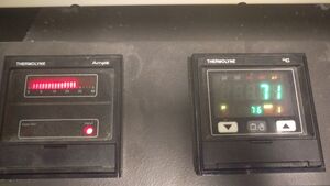
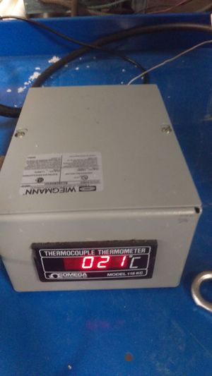
[[Image:High_temperature_Check.jpg|thumb|right|Thermocouple - furnace temperature verification]] | [[Image:High_temperature_Check.jpg|thumb|right|Thermocouple - furnace temperature verification]] | ||
==Programming== | |||
# Multiple programs can be added and run consecutively | |||
==Operation & Procedure== | ==Operation & Procedure== | ||
Revision as of 15:31, 23 January 2019

- Blah blah blah
Introduction
Provide a background on the method - link to wikipedia or elsewhere.
- Blah blah blah
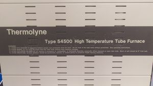
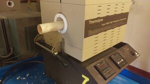
Temperature Tube Furnace
Safety
- Safety training for both use of gas cylinders and the labs must be completed.
- Safety glasses and long pants must be worn at all times.
- Fume hoods must be on during all operation when gasses are used.
- Tubes are made out of ceramic material, alumina in his case, and are affected by thermal shock. Therefore, heating rates no more than 10C are allowed.
- Furnaces are hot during operation, thus only remove samples after they have returned to room temperature.
Equipment or Bill of Materials
- Blah blah blah
List of necessary components to set up the assembly
Calibration & Tolerances
- Blah blah blah
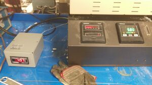
Programming
- Multiple programs can be added and run consecutively
Operation & Procedure
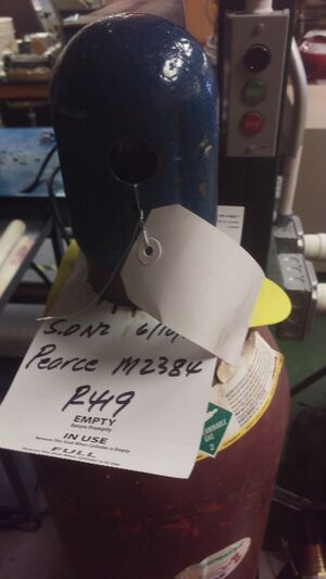
1. First the correct cover gas for heat treatment must be selected. In this example nitrogen gas is used to create an inert environment to prevent oxygen from reaching the samples. While moving cylinders it is imperative to keep the cap on until completely secured where it will be used.
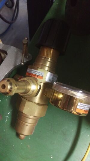
2. This is an example of the Primary regulator used on the previous gas cylinder. When in operation this regulator should be completely opened in order to ensure optimum gas flow. The gas volumetric flow will be controlled via a secondary regulator. This is to limit exposure to changing the primary regulator and for increased precision.
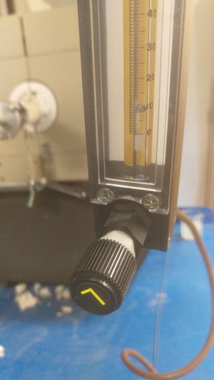
3. The secondary regulator has a metal ball which gains height as the flow of gas increases. The units used do depend on the gas specifically, however it is easy to simply use the height as a relative scale for and measure the gas flow through water and limiting the flow until the correct amount of bubbles is obtained.
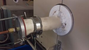
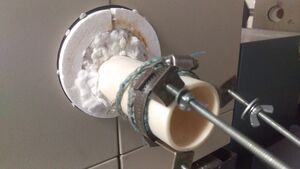
4. Once the alumina tube has been inserted into the furnace, clamps with a cloth belt are added to the ends. Pictured is the out-gas end. The cloth belt is necessary to distribute the compression force exerted onto the brittle alumina tube.

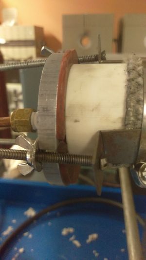
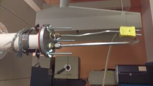
5. Clamps and cloth belt are also placed on the gas-in side as well as a copper tube to transfer the gas from the cylinder is added. This section will not be replaced through normal testing and should remain connected and sealed at all times.
6.
- Blah blah blah
- Blah blah blah
- Blah blah blah
- Blah blah blah
- Blah blah blah
- Blah blah blah
