| Line 746: | Line 746: | ||
Initially we have: | Initially we have: | ||
:Concentration of solution = 0.46 | : Concentration of solution = 0.46 | ||
:Total weight of solution = 33.281 lbs | : Total weight of solution = 33.281 lbs | ||
:Weight of ammonia = 15.309 lbs | : Weight of ammonia = 15.309 lbs | ||
:Weight of water = 17.972 lbs | : Weight of water = 17.972 lbs | ||
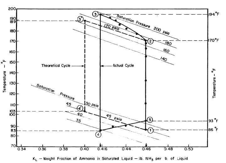
After regeneration the final concentration of the solution in the collector-generator is 0.416, as shown in Fig. 4.11. | After regeneration the final concentration of the solution in the collector-generator is 0.416, as shown in Fig. 4.11. | ||
:<math>\frac{ Weight of ammonia} {Weight of ammonia + Weight of water} = 0.416 </math> | :<math>\frac{ Weight of ammonia} {Weight of ammonia + Weight of water} = 0.416 </math> | ||
Since | |||
: The weight of water = 17.972 lbs, | |||
: Weight of ammonia in solution = 12.800 lbs. | |||
Therefore | |||
: Amount of ammonia distilled = 2,509 lbs. | |||
The amount of ammonia distilled was also determined by observing the liquid level in the receiver. Fig. 4,15 shows the geometry of the cross section, of the receiver. | |||
Let | |||
: A be the cross section area of the liquid, | |||
: R be the radius of the receiver cross section, | |||
: h be the height of the liquid level above the center of the receiver, | |||
: 1 be the length of the receiver; | |||
Also, let v be the volume of the drain pipe below the receiver. | |||
Then the volume of the liquid is equal to Al + v. | |||
===Cooling Ratio === | ===Cooling Ratio === | ||
Revision as of 02:21, 24 January 2010
The Design and Development of a Solar Powered Refrigerator
R.H.B. Exell, Sommai Kornsakoo, D.G.D.C Wijeratna. Bangkok, Thailand: Asian Institute of Technology, 1976.
Attention! Attention! Attention! Attention! Attention! Attention! Attention! Attention! Attention! Attention! Attention! Attention! Attention! Attention! Attention! Attention! Attention! Attention! Attention! Attention! Attention! Attention! Attention! Attention! Attention! Attention! Attention! Attention! Attention! Attention! Attention! Attention! Attention! Attention! Attention! Attention! Attention! Attention! Attention! Attention! Attention! Attention! Attention! Attention! Attention! Attention! Attention!
Note for everyone in Group 17. When you upload the figures, please name them in the format of "G17fig.2.6 . jpg" Since everyone is going to upload figures in a common file, so it may be mixed up with the others. If you are wondering how to type math equation in HTML (this), you can take a look by my part below. I went to Wiki, found a page with a lot of formulas and learn from their script. Simon
Preface
This research report describes work on the development of a solar powered refrigeration system which will eventually lead to the production of a village size ice maker or to a cold storage unit for food preservation.
This subject was examined by Mr. D.G.D.C. Wijeratna in his Individual Studies Project Report (No. 34), and the experimental unit was designed by Dr. R.H.B. Exell. The construction and testing of the unit was by Mr. Sommai Kornsakoo for his Master Degree Thesis.
The Asian Institute of Technology (AIT) is indebted to the John F. Kennedy Foundation, Thailand, for financial support in the form of a grant for solar energy research made in response to a proposal made in 1973 by Professor H.E. Hoelscher, President of AIT, to Dr. Tbanat Khoman, Chairman of the Foundation.
Summary
A small ammonia-water intermittent absorption refrigerator with a 1.44 m2 flat plate solar collector has been tested as a first step towards the development of a village ice maker. No oil or electricity is used. Regeneration takes place during the day and refrigeration at night. Rapid absorption is obtained by means of a new feature, first proposed by Swartman, in which the heat of absorption is dissipated from the flat plate.
In the generator 15 kg of solution containing 46% ammonia in water are used. On a clear day the solution temperature rises from 30oC, to 88oC and 0.9 kg of pure ammonia is condensed at 32oC. During refrigeration the temperature of the ammonia drops to -7oC. The estimated overall solar coefficient of performance (cooling effect divided by solar heat absorbed) is 0.09, which though small is comparable with previously published work. Developments in the design are discussed.
Contents
I INTRODUCTION
- The Basis for Considering Solar Energy
There are several important reasons for considering solar energy as an energy resource to meet the needs of developing countries. First, most the countries called developing are in or adjacent to the tropics and have good solar radiation available. Secondly, energy is a critical need of these countries but they do not have widely distributed, readily available supplies of conventional energy resources. Thirdly, most of the developing countries are characterised by arid climates, dispersed and inaccessible populations and a lack of investment capital and are thus faced with practically insuperable obstacles to the provision of energy by conventional means, for example, by electrification. In contrast to this solar energy is readily available and is already distributed to the potential users. Fourthly, because of the diffuse nature of solar energy the developments all over the world have been in smaller units which fits well into the pattern of rural economics.
- Objectives of the Study
- Possibilities for Research and Development
- The Rationale for Selecting Solar Refrigeration
II SOLAR REFRIGERATION
Indices of Performance
Operation of the Intermittent Ammonia-Water System
Analysis of the Ideal Cycle
Rigorous Analysis of the Ammonia-Water Cycle
Page 20 goes here Graham.
-15-
where
- = mean latent heat of the refrigerant during the process 6-1.
- = weight on the refrigerant at point 6.
The heat supplied during the regeneration process 1-3-4 is given by
where
- = weight of the solution, suffix indicating the point of the cycle,
- = specific enthalpy of the solution, suffix indicating the point of the cycle,
- = specific enthalpy of the vapor boiling out of the liquid,
- = differential mass of the vapor boiling out of the liquid.
- Thus the expression for the C.O.P. becomes
Historical Development
According to the Survey of Solar-Powered Refrigeration carried out by SWARTMAN, HA, and NEWTON (1973), the first study undertaken to explore the use of solar energy for refrigeration was probably in 1936 at the University of Florida by Green. The steam to power a steam jet refrigerator was produced by heating water flowing in a pipe placed at the focal line of a cylindro-parabolic reflector.
-16-
Oniga reported in 1937 that researchers in Brazil tried to adapt a parabolic reflector to an absorption refrigerator but the system never got beyond the experimental stage.
Kirpichev and Baum of Russia reported the successful operation of an assembly of solar refrigerators producing 250 kilogrammes of ice per day in 1954. The refrigerators were of the conventional vapour – compression type driven by a heat engine operating on the steam produced by a boiler placed at the focus of a large mirror. However, it has been generally conceded that the low efficiency of solar energy in producing power, the very high cost of equipment, and the complexity of this type of system are unfavourable factors in the future development. Since this system was build, there has been little interest shown in this direction of solar refrigeration.
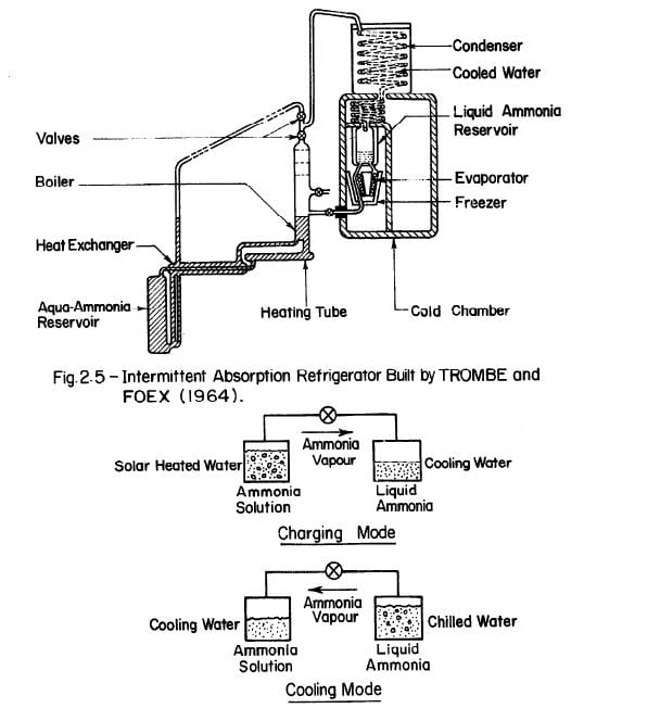
The first major project on an all solar absorption refrigeration system was undertaken by TROMBE and FOEX (1964). Fig. 2.5 shows the general set-up of the system, which has these main features: ammonia-water solution is allowed to flow from a cold reservoir through a pipe placed at the focal line of a cylindro-parabolic reflector. Heated ammonia-water vapourized in the boiler is subsequently condensed in a cooling coil. The evaporator is a coil surrounding the container used as an ice box. The cylindro-parabolic reflector measured 1.5m2. In the prototype trials, the daily production of ice was about 6 kilogrammes or about 4 kilogrammes of ice per square metre of collecting area for four – hour heating.
-17-
Fig. 2.6 - The Basic Solar-Powered Intermittent Absorption Refrigerator
-18-
The design by Trombe and Foex is very promising and should be studied further although modifications may be necessary on the solar collector, boiler, and condenser.
Williams and others at the University of Wisconsin built a small food cooler in 1957 intended for use in underdeveloped rural areas. The apparatus consisted of two vessels linked together by a pipe as shown in Fig. 2.6. The energy was provided by a parabolic mirror of moulded 1.27 mm polystyrene with an aluminized mylar polyester film and stiffened at the rim by metal tubing. Ammonia-water and R-21-glycol ether were used as working solutions. This study showed that refrigeration can be achieved by the use of intermittent absorption refrigeration cycles. Although performance is limited by the characteristics of the intermittent cycle, the simplicity of the system accounts for the low temperature obtained in the evaporator. Finally, the study showed that ammonia-water has a superior performance over R-21-glycol ether in an intermittent refrigeration system.
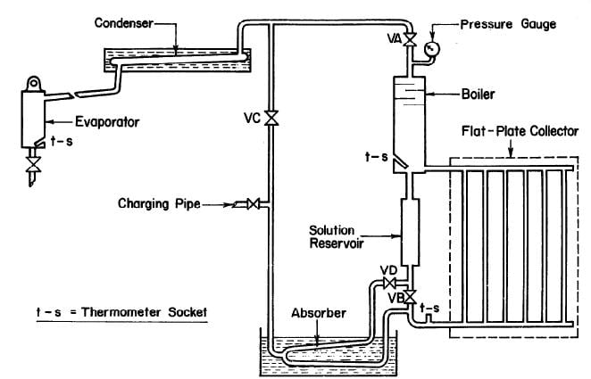
CHINNAPPA (1962) built a simple intermittent refrigerator operated with a flat-plate collector at Columbo, Ceylon as shown in Fig. 2.7. The generator-absorber in this refrigerator was of welded pipe construction and incorporated with a flat-plate collector and a water cooled absorber. The solar collector was a copper sheet measuring 152.4 cm by 106.7 cm, 0.76 mm thick, and painted black. The plate was solded to six 6.35 cm diameter steel pipes and the pipes were welded to headers. There were three glass covers on the collector which were supported by strips of cork board. An ammonia-water solution was used as the working fluid.
-19-
Fig. 2.7 - Schematic of Solar Refrigerator Operated with Flat-Plate Collector by CHINNAPPA (1962)
-20-
While it has been generally expected that the flat-plate collector would be more suitable for the lower temperature of generation required in air conditioning, tests in the investigation by CHINNAPPA (1962) indicated that it is possible to use a flat-plate collector incorporated with the generator to produce cooling at a temperature as low as -12°C. It is noted that ice can be produced in this refrigerator at one kg a day per 0.7 m2 of solar collecting surface. Results in this investigation were not spectacular, but they showed that a simple intermittent refrigerator using a low temperature heat collecting device such as the flat-plate collector can achieve cooling.
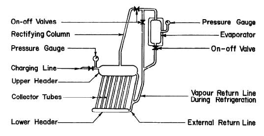
SWARTMAN and SWAMINATHAN (1971) built a simple, intermittent refrigeration system incorporating the generator-absorber with a 1.4 m2 flat-plate collector at the University of Western Ontario. Fig. 2.8 shows the system schematically. The collector-generator assembly consisted of 1.27 cm steel pipes connecting a 5.1 cm feeder and 15.2 cm header. Thin copper sheet was soldered to the tubes and the whole assembly was enclosed in a wooden box with insulation material at the bottom and a two-layered glass cover on the top. Ammonia water solutions of concentration varying from 58 to 70 percent were tested. Tests were relatively successful; evaporator temperatures were as low as -12°C, but due to poor absorption, the evaporation rate of ammonia in the evaporator was low.
Another study at the University of Western Ontario in 1970 investigated an ammonia-sodium thiocyanate solution in the same system as that described above. Results of the investigation showed that the coefficients of performance for NH3 -NaSCN range from 0.11 to 0.27 compared with 0.05 to 0.14 for NR3-H20 obtained from the earlier study, Nevertheless, the system was
-21-
Fig. 2.8 - Intermittent Solar Refrigerator Built at University of Western Ontario
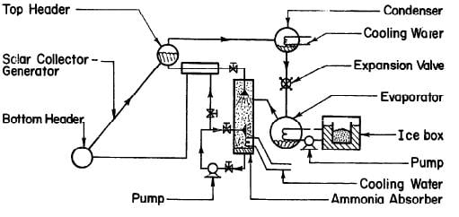
Fig. 2.9 - Solar Ice Maker Built at the University of Florida by FARBER (1970)
-22-
still unable to make any considerable amount of ice at the evaporator. It was concluded that NH3-NaSCN has a better performance than that NH3-H20. It also offered lower equipment cost as it did not need a rectifying column due to the low volatility of the NaSCN salt. An optimal concentration of 54% was suggested for intermittent refrigeration.
FARBER (1970) has built the most successful solar refrigeration system to date. It was a compact solar ice maker using a flat-plate collector as the energy source. Fig. 2.9 shows the flow diagram of the system. The solar collector-generator was 1.49 m2, consisting of a 6.35 cm top header. The 2.54 cm pipes were spaced on 10.2 cm centres and soldered to a 20 gauge galvanized iron sheet. This unit was placed in a galvanized sheet metal box with a single glass cover and one inch of Styrofoam insulation behind the absorber-generator element. In addition to the usual components, such as condenser, evaporator, ice box, heat exchanger, there was an ammonia absorbing column of the shell-and-tube type and two pumps to circulate the liquid ammonia and chilled water in the evaporator. It was reported that an average of about 42,200 kJ of solar energy was collected by the collector per day and ice produced was about 18.1 kilogrammes. This gave an overall coefficient of performance of about 0.1 and 12.5 kilogrammes of ice per m2 of collector surface per day.
As far as solar refrigeration is concerned, this has been the most successful system, but it should be noted that the system was not totally solar-powered as there were two pumps operated by electricity. The system would not work in areas where electricity is not available.
III DESIGN OF THE EXPERIMENTAL UNIT
Choice of Configuration
-23-
It was stated earlier that a solar refrigerator consists of two components, a solar power unit and a refrigeration unit. The solar power unit is based on either of two basic concepts, i.e., flat-plate collectors or focussing collectors.
Flat-plate collectors are flat blackened surfaces to absorb direct and diffuse solar radiation. Transparent covers and back insulation may be provided to reduce or control heat losses from the plate. On the plate, absorbed solar energy is converted to a desired form of energy, usually heat, and means are provided to remove that energy, usually as heated water or air. Flat-plate collectors are generally suitable for operation in a fixed position.
The basic element of the focussing collector is an optical device, e.g., a parabolic reflector, to focus the beam component of solar radiation on a receiver smaller than the reflector. This collector can produce a higher energy flux. Although the focussing collector gives higher temperatures than the flat-plate collector, it is more difficult to operate. Also, for a small experimental -unit, it seems to be more expensive than the flat-plate collector, Therefore, a flat-plate collector was selected for this particular study.
The refrigeration unit can be either a continuous or an intermittent absorption system. The continuous absorption refrigeration system cannot serve the purpose if the pumps require power. Therefore, in rural areas where electricity is unavailable, the intermittent absorption refrigeration
-24-
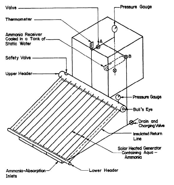
system is preferred. The intermittent refrigeration cycle has two major operations, regeneration and refrigeration. Regeneration is the process of heating the refrigerant-absorbent fluid to drive off the refrigerant vapour and condense the vapour in a separate container. Refrigeration takes place when the liquid refrigerant vapourizes, producing a cooling effect around the evaporator. The refrigerant is re-absorbed by the absorbent. Since the refrigerator is a purely experimental device it was decided to keep it as simple as possible. The configuration chosen is shown in Fig. 3.1. Simplicity has been achieved by having the condenser function as the evaporator and the generator function as the absorber.
Operation of the System
During the regeneration, valve A is open and valve B is closed, and the strong solution in the generator being heated by the flat-plate collector boils, producing vapour at a high pressure. The weak solution returns from the top header to the bottom header by the insulated return pipes. The vapour in the top header is mainly ammonia because water has a much lower volatility than ammonia. The ammonia vapour passes into the condenser which is immersed in a tank of cold water to keep it cool. The pressure is uniform throughout the system. When heating stops valve A is closed and the vapour pressure in the generator drops. The concentration in the generator is now less than it was before regeneration. Before refrigeration is started the tank of cooling water is removed and valve B is opened. The condenser now functions as the evaporator. Ammonia vapourizes due to the pressure difference between the generator and evaporator. The vapourization of ammonia absorbs heat from
-25-
Fig. 3.1 - The First Experimental Unit
-26-
the surroundings of the evaporator, thus producing the refrigeration effect. Ammonia vapour from the evaporator passes through the pipe taken to the bottom header of the generator so that the incoming vapour bubbles through the aqua-ammonia solution thus facilitating absorption in it. The glass covers are removed from the collector so that the heat of absorption can be dissipated to the sky from the generator risers. Refrigeration continues until all the liquid ammonia in the evaporator has vapourized. A full cycle of operation has now been completed. To accommodate the intermittent availability of solar energy, the refrigeration is carried out during the day and refrigeration takes place at night after the radiation is no longer available.
Concentration of Aqua-Ammonia
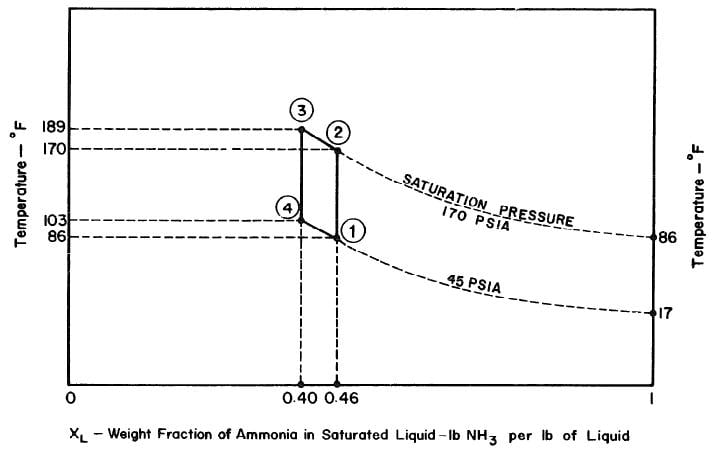
The objective is to produce a temperature of 17°F in the evaporator, The saturation vapour pressure of anhydrous ammonia at this temperature is 45 psia. The temperature of the absorber is the atmospheric temperature which is assumed to be 86°F. Thus in the absorber there is an aqua-ammonia mixture at temperature of 86'F with the pressure of ammonia vapour at 45 psia. Hence, from the p-t-x diagram for aqua-ammonia the concentration is found to be 0.46, thus determining the starting point of refrigeration cycle, shown as point 1 in Fig. 3.2.
Regeneration Phase of the Cycle
The condenser temperature is 86°F. From the p-t-x diagram the saturation pressure of anhydrous ammonia at this temperature is 170 psia. Point 2 of the cycle can be determined, since the pressure and the concentration (which
-27-
Fig. 3.2 - Ideal Thermodynamic Cycle
-28-
does not change during process l-2) at point 2 are known. Point 3 of the cycle is fixed by the maximum solution temperature attainable with the collector, which is assumed to be 189°F. This determines point 3 and hence the concentration which is 0.40 from the p-t-x diagram.
Refrigeration Phase of the Cycle
Ideally, during the refrigeration phase of the cycle, the solution is first cooled to the absorption pressure of 45 psia, which at a concentration of 0.40 corresponds to an initial absorption temperature of 103°F. This fixes point 4. The cycle is completed by the process 4-l during which ammonia evaporating at 17°F is reabsorbed into the solution.
Collector-Generator Specifications
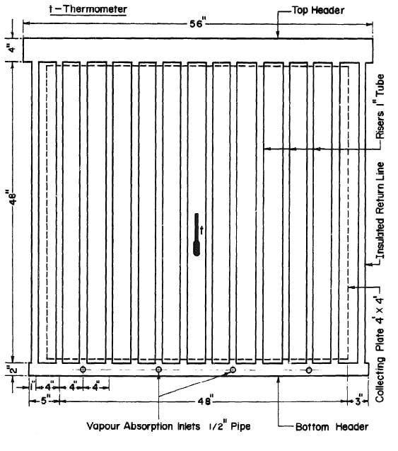
It was decided to keep the unit as compact as possible. Thus, a four ft. by four frontal area was selected for the collector-generator. Black iron seamless pipes were used throughout to resist corrosion by ammonia-water mixture and the pressure associated with the necessarily high ammonia concentrations. A copper sheet four by four feet and 0.06 inch thick was used for the collecting plate and was painted dull black. The plate was soldered to twelve 1 inch diameter tubes at four-inch intervals. The ends of the 1 inch tubes were welded to headers. To provide for adequate separation of the water from the ammonia vapour out of the collector-generator, a 4-inch pipe was used for the top header, This 56 in, length of pipe gave a liquid surface area of 225 in2 when the header was half full. The liquid level could be observed through bull's eyes at both ends of the header. For the bottom header a pipe 2 inches in diameter and 54 inches long was used. The arrangement of the collector-generator is shown in Fig. 3.3.
-29-
Fig. 3.3 - Solar Collector - Generator
-30-
To prevent heat loss at the rear of the collector-generator polystyrene foam four inches thick was used for insulation. The top and bottom headers and the risers at each end of the collector were also thermally insulated with polystyrene foam. There were two glass covers in front of the collecting surface supported by a wooden frame. Ordinary window glass 1/4 in thick was used. The gap between the collecting tubes and the first glass cover was 1/4 in; between the two glass covers the gap was 3/4 in. The glass covers were removable.
The inclination of the plane of the generator was 20 degrees to the horizontal with the unit facing due south.
The Volume of the Generator
The volume of the generator calculated below from the standard pipe dimensions is used to determine the quantity of aqua-ammonia in the system, and to determine the changes in the liquid level in the generator throughout the cycle.
Top header (half full)
4.667 ft x 0.5 x 0.0882 ft3/ft = 0.206 ft3
14 risers
14 x 4 ft x 0.00585 ft3/ft = 0.328 ft3
Bottom header
4.5 ft x 0.0233 ft3/ft = 0.105 ft3
Total volume = 0.639 ft3
-31-
Surface area of the liquid in the top header half full
= ID. X length
= 4.026 in x 56 in
= 225.456 in2
= 1.565 ft2
Specific Volume of aqua-ammonia
At point 1, V1 = 0.0192 ft3/lb
Point 2, V2 = 0.0205ft3/lb
Point 3, V3 = 0.0202 ft3/lb
Point 4, V4 = 0.01895 ft3/lb
Liquid level in generator
Start with 0.639 ft3 of 0.46 aqua-ammonia at 86°F
Its weight is 0.639/0.0192 = 33.281 lbs
The volume of 33.281 lbs of 0.46 aqua-ammonia at 170°F is
33.281 x 0.205 = 0.682 ft3
Increase in volume is 0.682 – 0.639 = 0.043 ft3
Rise in liquid level is 0.043/1.565 = 0.027 ft
= 0.331 in
When concentration, X = 0.46
Wt. Of ammonia + wt. of water = 33.281 lbs
Therefore, wt. of ammonia = 15.309 lbs
wt. of water = 17.972 lbs
When concentration X = 0.40
wt. of ammonia = 11.981 lbs
wt. of water = 17.972 lbs
Total weight = 29.953 lbs
-32-
Therefore, wt. of ammonia distilled = 3.328 lbs.
After the distillation of 3.328 lbs of ammonia we have 29.958 lbs of 0.40 aqua-ammonia at 139°F
Volume = 29.953 x 0.0202 = 0.605 ft3
Decrease in volume below initial volume at point 1 is 0.034 ft3.
Fall in liquid level below centre is 0.034/1.565 = 0.022 ft
= 0.261 in.
Volume of 29.953 lbs of aqua-ammonia at 103°F is 29.953 x 0.01895
= 0.568 ft3
Decrease in volume below initial volume at point 1 is 0.071 ft3.
Fall in liquid level below centre is 0.071/1.565 = 0.045 ft
= 0.544 in.
The Size of the Receiver for Ammonia
Weight of ammonia distilled
= 3.328 lbs
This ammonia has volume (at 86°F) = 3.328/37.16 = 0.089 ft3.
Let the ammonia receiver be made of Schedule 40, 4-inch pipe.
Required length = 0.089/0.0882 = 1.015 ft = 12.18 in.
Consequently, the ammonia receiver (condenser-evaporator) was made of 4 inch black iron pipe, 16 inches long.
Heat of Generation
Let enthalpy of 29.953 lbs of 0.40 aqua-ammonia at 189°F = H3,
enthalpy of 3.328 lbs of ammonia vapour at mean generation temperature
(approximately) 178° = HA,
enthalpy of 33.281 lbs of 0.46 aqua-ammonia at 86°F = H1.
-33-
From fig. 3.2: Hl = 33.281 x (-55) = -1830 Btu.
HA = 3.328 x 627 = 2086 Btu.
H3 = 29.953 x 75 = 2246 Btu.
Therefore, heat of generation = H3 + HA – Hl = 6162 Btu.
Daily global solar radiation on horizontal surface = 400 Cal.cm.-2day -1
= 22,800 Btu on 4 by 4 feet surface per day
Therefore, the solar energy incident on the collector is 3.7 times the heat of generation.
Heat of Condensation
After rectification the ammonia has a temperature of 120°F.
Enthalpy of 3.328 lbs of ammonia vapour at temperature 120°F
= 3.328 x 634 = 2110 Btu.
Enthalpy of 3.328 lbs of ammonia liquid at pressure 170 psia and
temperature 86°F = 3.328 x 138.9 = 462 Btu.
Total heat of condensation = 2110 - 462 = 1648 Btu.
The condenser was kept at a temperature constant within 1°F by immersing it in 135 gallons (80 x 80 x 80 cm3) of cold water during the generation cycle. The water tank was supported by a wooden stand.
Further Details of the Design
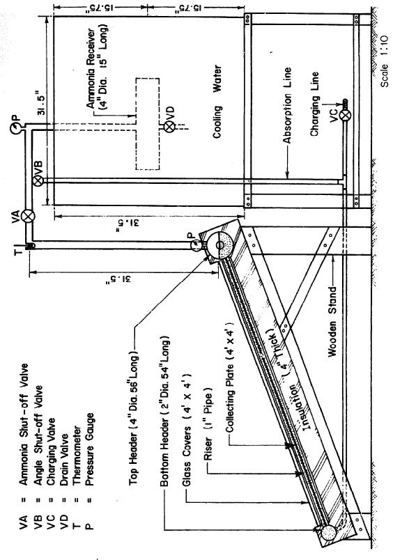
A 1-inch pipe was used to connect the generator to the ammonia reservoir. A 28 in. length of this pipe rising vertically from the top header was used as a rectifier to remove water from the ammonia being distilled. The absorption line was made of ¼ in pipe connected to the bottom header as shown in Fig. 3.4.
-34-
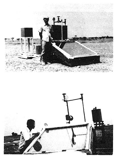
Fig. 3.4 - Small Solar Powered Refrigerator
-35-
Fig. 3.4 -Solar-Powered Refrigerator
-36-
There were two ammonia shut-off valves to control the system. The pressure in the system was indicated by two bourdon-type ammonia gauges; one was attached to the generator and the other was at the top of the tube leading to the ammonia receiver. A thermometer was also used at the top of the rectifier to measure the temperature of the ammonia vapor.
IV EXPERIMENTAL TESTS
Relationship between Plate Temperature and Solution Temperature
-37-
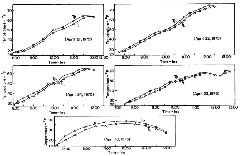
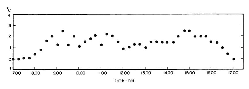
The collector-generator was first charged with water and temperature measurements were made to find the relation between the plate temperature (TT )and solution temperature (TL). Five tests runs were carried out (see Fig.4.1). It was concluded that the solution temperature was lower than the corresponding plate temperature by about 2.4°F. However, it was observed that at the beginning and end of each day both temperatures were the same.The average values of the temperature differences TP-TL are shown in Fig. 4.2.This calibration was necessary because no high pressure thermometer fitting had been attached to the generator for measuring internal temperatures.
Experimental Results
-37-
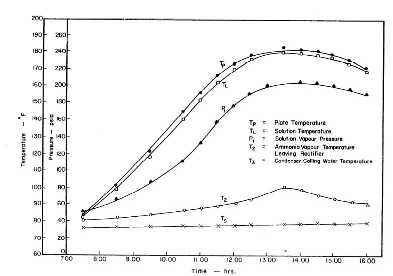
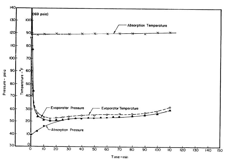
After evacuation, the system was charged with 0,46 aqua-ammonia solution (see Appendix A). The results obtained during four test runs are shown in Figures 4.3 to 4.14. These runs were performed on nearly cloudless days.
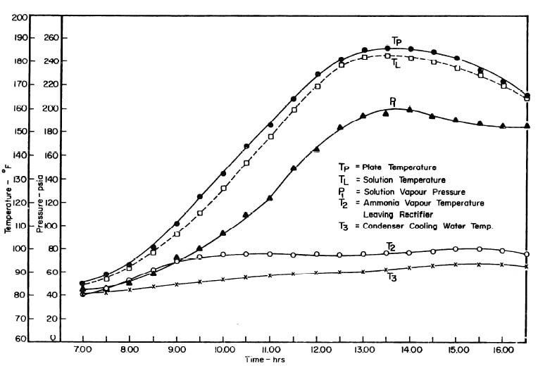
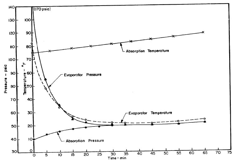
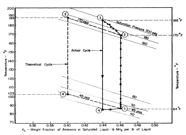
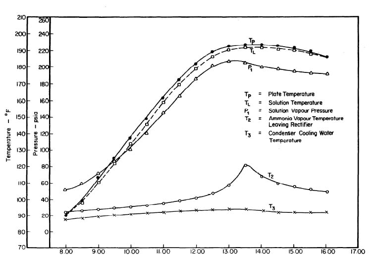
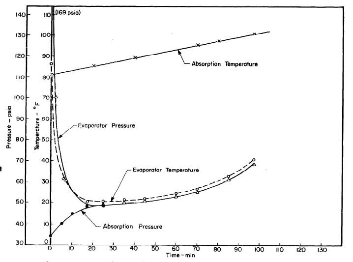
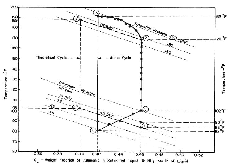
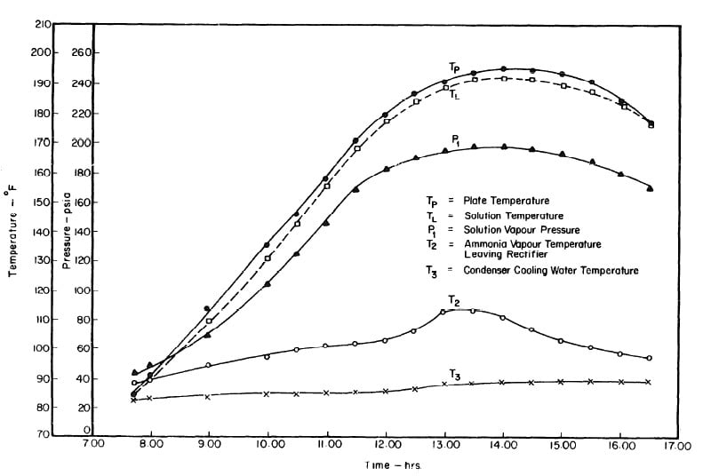
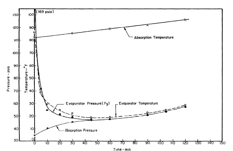
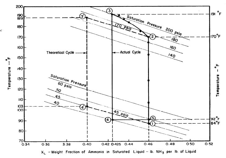
Illustrated in Fig. 4.3 are the plate temperature (Tp), the solution temperature (TL)derived from the calibration shown in Fig. 4.2, the solution vapor pressure (Pl), ammonia-vapor temperature when leaving rectifier (T2),and condenser cooling water temperature (T3) during the generation period. The evaporator pressure, evaporator temperature derived from the pressure, absorption pressure, and absorption temperature for the refrigeration period are shown in Fig. 4,4. The theoretical and actual cycles executed by the solution in the collector-generator are shown as l-2-3'-4' and l-2-3-4-5 respectively in Fig. 4.5.
-38-
Fig. 4.1 - Observation on Plate and Solution Temperatures
-39-
Fig. 4.2 - Differences between Plate and Solution Temperature (TP-TL) : Mean of Five Test Runs.
-40-
Fig. 4.3 - Observation during Refrigeration test on May 9, 1975
-41-
Fig. 4.4 - Observation during Refrigeration test on May 9, 1975
-42-
Fig. 4.5 - Actual and Theoretical Solution Cycles for Test on May 9, 1975
-43-
Fig. 4.6 - Observations during Regeneration Test on May 10, 1975
-44-
Fig. 4.7 - Observations during Refrigeration Test on May 10, 1975
-45-
Fig. 4.8 - Actual and Theoretical Solution Cycles for Test on May 10, 1975
-46-
Fig. 4.9 - Observations during Regeneration Test on May 14, 1975
-47-
Fig. 4.10 - Observations during Refrigeration Test on May 14, 1975
-48-
Fig. 4.11 - Actual and Theoretical Solution Cycles for Test on May 14, 1975
-49-
Fig. 4.12 - Observations during Regeneration Test on May 17, 1975
-50-
Fig. 4.13 - Observations during Refrigeration Test on May 17, 1975
-51-
Fig. 4.14 - Actual and Theoretical Solution Cycles for Test on May 17, 1975
-52-
The analysis of the test on may 14th 1974 9Figure 4.9,4.10, and 4.11) is given as an example below.
Amount of Ammonia Distilled
Initially we have:
- Concentration of solution = 0.46
- Total weight of solution = 33.281 lbs
- Weight of ammonia = 15.309 lbs
- Weight of water = 17.972 lbs
After regeneration the final concentration of the solution in the collector-generator is 0.416, as shown in Fig. 4.11.
Since
- The weight of water = 17.972 lbs,
- Weight of ammonia in solution = 12.800 lbs.
Therefore
- Amount of ammonia distilled = 2,509 lbs.
The amount of ammonia distilled was also determined by observing the liquid level in the receiver. Fig. 4,15 shows the geometry of the cross section, of the receiver.
Let
- A be the cross section area of the liquid,
- R be the radius of the receiver cross section,
- h be the height of the liquid level above the center of the receiver,
- 1 be the length of the receiver;
Also, let v be the volume of the drain pipe below the receiver. Then the volume of the liquid is equal to Al + v.
Cooling Ratio
Heat Absorbed by Solution During Regeneration
Solar Coefficient of Performance
Discussion
V CONCLUSIONS AND PLANS FOR CONTINUING RESEARCH
- Conclusions
- Economic Considerations
- Modifications
- The Development of a Village Ice-Maker
- Alternatives
References
Appendix A
- Charging - Equipment - Procedure
Appendix B
- Estimation of Incident Solar Radiation


