Tinning is the practice of wetting a surface with solder. In this context, it is the wetting of the exposed conductors, which is recommended as loose strands can inadvertently cause short circuits and are inherently more difficult to control than a single cohesive unit.
Tinning is the practice of wetting a surface with solder. In this context, it is the wetting of the exposed conductors, which is recommended as loose strands can inadvertently cause short circuits and are inherently more difficult to control than a single cohesive unit.
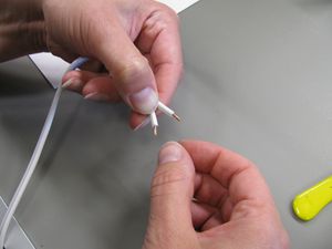
#[[File:MOST_Delta_007.JPG|thumb|right|Stripped conductor twisting.]]After stripping a small amount of insulation from the end of the conductor, twist the strands together and dip into solder flux, applying a light coating of flux to the bare metal.
#[[File:MOST_Delta_007.JPG|thumb|right|Stripped conductor twisting.]]After stripping a small amount of insulation from the end of the conductor, twist the strands together and dip into solder flux, applying a light coating of flux to the bare metal.
#Solder the prepared strands together.
#Solder the prepared strands together.
{{clear}}
{{clear}}
=Butt Solder Joints=
==Butt Solder Joints==
All of the butt joints on the MOST Delta are located on the end effector where the heating resistor leads are connected to the power conductors and the thermistor leads and fan are connected to copper pairs. A "third hand" (either literal or the tool) greatly facilitates butt joining.
All of the butt joints on the MOST Delta are located on the end effector where the heating resistor leads are connected to the power conductors and the thermistor leads and fan are connected to copper pairs. A "third hand" (either literal or the tool) greatly facilitates butt joining.
Line 48:
Line 58:
#Slide the heat shrink tubing over the joint and overlapping insulators on both sides of the joint. Shrink the tube in place.
#Slide the heat shrink tubing over the joint and overlapping insulators on both sides of the joint. Shrink the tube in place.
=Soldering Copper Pair to Limit Switches=
==Soldering Copper Pair to Limit Switches==
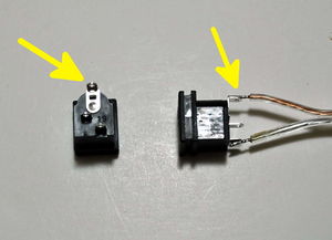
The limit switches have three terminals, one is common and the other two are normally open or normally closed. The controller firmware expects normally closed, which requires the conductors be soldered to the outermost two terminals, leaving the center terminal alone. Again, a "third hand" is helpful.
The limit switches have three terminals, one is common and the other two are normally open or normally closed. The controller firmware expects normally closed, which requires the conductors be soldered to the outermost two terminals, leaving the center terminal alone. Again, a "third hand" is helpful.
Line 57:
Line 67:
#[[File:MOST_Delta_009.JPG|thumb|right|Heat shrink tubing on limit switch.]]Slide the heat shrink tubing over the terminal and shrink in place.{{clear}}
#[[File:MOST_Delta_009.JPG|thumb|right|Heat shrink tubing on limit switch.]]Slide the heat shrink tubing over the terminal and shrink in place.{{clear}}
=Solder Extension to Fan Wires=
==Solder Extension to Fan Wires==
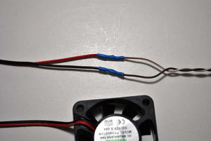
# [[File:MOST_Delta_fan_polarity.JPG|thumb|right|Solder extension to fan wires.]]Strip and tin both ends of a 1m length of 24ga twisted pair.
# [[File:MOST_Delta_fan_polarity.JPG|thumb|right|Solder extension to fan wires.]]Strip and tin both ends of a 1m length of 24ga twisted pair.
# If the 40mm fan has a header on the wires, snip it off with wire cutters. Strip and tin the fan wires.
# If the 40mm fan has a header on the wires, snip it off with wire cutters. Strip and tin the fan wires.
Line 64:
Line 74:
# Move the heat shrink tubing over the solder joint and shrink in place.{{clear}}
# Move the heat shrink tubing over the solder joint and shrink in place.{{clear}}
=Solder Power Cable to Barrel Connector=
==Solder Power Cable to Barrel Connector==
# [[File:MOST_Delta_barrel_connector_polarity.JPG|thumb|right|The positive terminal on the barrel connector is marked.]]Strip and tin both ends of a 15cm (6 inch) length of 18ga speaker wire or lamp cord.
# [[File:MOST_Delta_barrel_connector_polarity.JPG|thumb|right|The positive terminal on the barrel connector is marked.]]Strip and tin both ends of a 15cm (6 inch) length of 18ga speaker wire or lamp cord.
# As with the limit switches, place a small pad of solder on the positive and negative terminals of the barrel connector. The positive terminal is the largest of the three terminals.
# As with the limit switches, place a small pad of solder on the positive and negative terminals of the barrel connector. The positive terminal is the largest of the three terminals.
# Solder the on pair of tinned ends of the speaker wire or lamp cord to the pads.{{clear}}
# Solder the on pair of tinned ends of the speaker wire or lamp cord to the pads.{{clear}}
=Strip and Tin Motor Wires=
==Strip and Tin Motor Wires==
# If the motor wires come with a header attached, snip it off with wire cutters.
# If the motor wires come with a header attached, snip it off with wire cutters.
Tinning is the practice of wetting a surface with solder. In this context, it is the wetting of the exposed conductors, which is recommended as loose strands can inadvertently cause short circuits and are inherently more difficult to control than a single cohesive unit.
Video instructions
Soldering and Tinning
Error in widget YouTube: Unable to load template 'wiki:YouTube'
Step-by-step instructions
Tinning Conductor
Stripped conductor twisting.After stripping a small amount of insulation from the end of the conductor, twist the strands together and dip into solder flux, applying a light coating of flux to the bare metal.
Solder the prepared strands together.
Butt Solder Joints
All of the butt joints on the MOST Delta are located on the end effector where the heating resistor leads are connected to the power conductors and the thermistor leads and fan are connected to copper pairs. A "third hand" (either literal or the tool) greatly facilitates butt joining.
Tin the conductors per instructions above.
Place adequate lengths of heat shrink tubing over one of the conductors and push it away from the solder joint so it doesn't shrink during soldering.
Align the tinned conductor with the conductor it is to be joined with such that the two are parallel and touching.
Solder the joint and blow on it to rapidly solidify the solder.
Slide the heat shrink tubing over the joint and overlapping insulators on both sides of the joint. Shrink the tube in place.
Soldering Copper Pair to Limit Switches
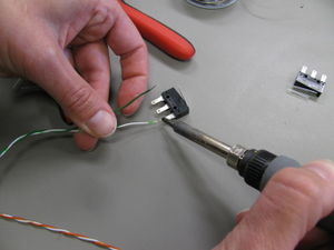
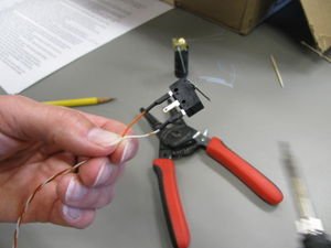
The limit switches have three terminals, one is common and the other two are normally open or normally closed. The controller firmware expects normally closed, which requires the conductors be soldered to the outermost two terminals, leaving the center terminal alone. Again, a "third hand" is helpful.
Tin the conductors per the instructions above.
Place a small solder puddle on the two outermost terminals of the limit switch.
Place adequate lengths of heat shrink tubing over the conductors and push it away from the solder joint so it doesn't shrink during soldering.
Soldering limit switch.Solder the conductors to the terminals at the puddles of solder. Blow on the joints to rapidly solidify the solder.
Heat shrink tubing on limit switch.Slide the heat shrink tubing over the terminal and shrink in place.
Solder Extension to Fan Wires
Solder extension to fan wires.Strip and tin both ends of a 1m length of 24ga twisted pair.
If the 40mm fan has a header on the wires, snip it off with wire cutters. Strip and tin the fan wires.
Cut a pair of small heat shrink tubes and slide one on each of the fan wires.
Keeping the heat shrink tube away from the joint, butt solder the twisted pair to the fan wires.
Move the heat shrink tubing over the solder joint and shrink in place.
Solder Power Cable to Barrel Connector
The positive terminal on the barrel connector is marked.Strip and tin both ends of a 15cm (6 inch) length of 18ga speaker wire or lamp cord.
As with the limit switches, place a small pad of solder on the positive and negative terminals of the barrel connector. The positive terminal is the largest of the three terminals.
Solder the on pair of tinned ends of the speaker wire or lamp cord to the pads.
Strip and Tin Motor Wires
If the motor wires come with a header attached, snip it off with wire cutters.


