No edit summary |
|||
| Line 51: | Line 51: | ||
|- | |- | ||
|} | |} | ||
== | ==Hardware Components== | ||
=====PV Panel===== | =====PV Panel===== | ||
A small C-Si PV panel is used to act as a light-controlled switch for the window shade, and also charge the battery. It was tested under bright light conditions and found to generate a no-load voltage upto 6V DC.<br /> | |||
=====DC-DC Converter===== | =====DC-DC Converter===== | ||
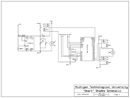
The Arduino Uno micro-controller requires 5V DC for power, so a DC-DC buck-boost converter is used to maintain a constant 5V voltage across the battery terminals. As the converter has to deal with low input voltages, The LT1073-5 was selected due to the few number of external components needed, as well as its low required input voltage (1V).<br /> | |||
=====Electric Motor===== | =====Electric Motor===== | ||
Due to its cheap cost, a small geared hobby motor was selected, utilizing a potentiometer for position feedback. The GM3 geared hobby motor provides up to .34 Nm of torque at rated voltage. <br /> | |||
===== | =====Battery===== | ||
For energy storage, a Li-ion battery will be used to provide 5V output to the micro-controller circuit and the motor. It's specifications are yet to be determined. <br /> | |||
==Future Works== | ==Future Works== | ||
Revision as of 18:01, 25 February 2014
Smart shade literature Review
here is the methods for smart shade project, go back to smart shade literature Review.
Methods
introducing the project:
During night, when window shades are left open, a lot of heat from the inside is lost. This project aims to implement photovoltaic cells in the shades such that they cause the shades to open and generate electricity during the day, and automatically close the shades at night. The key feature is the dual implementation of PV cells as power sources and as light sensors. Due to this, the heat lost during the night through windows can be conserved, which in-turn reduces the heating energy costs for buildings and improves their energy efficiency.[1-2]
General review of method
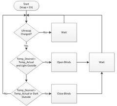
The logic is to compare the desired temperature to room temperature and opens or closes the blinds based on temperature difference. Rather than sensing temperature, this could also be done in another way, by sensing the amount of voltage produced by the PV cell, thereby gauging the amount of ambient light and controlling the shades based on that.

| required components | detail |
|---|---|
| DC Motor | GM3 |
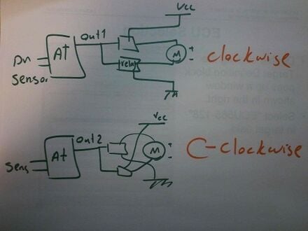
| SPDT Relay | For switching motor |
| SPST switch | For discharging Power storage |
| PV panel | Power source or sensor |
| Ultracapacitor or battery | Power storage |
| Controller | Arduino Uno |
| Power resistor | For discharging ultracapacitor |
| DC-DC Converter | |
| Fuse holder and Fuse |
Hardware Components
PV Panel
A small C-Si PV panel is used to act as a light-controlled switch for the window shade, and also charge the battery. It was tested under bright light conditions and found to generate a no-load voltage upto 6V DC.
DC-DC Converter
The Arduino Uno micro-controller requires 5V DC for power, so a DC-DC buck-boost converter is used to maintain a constant 5V voltage across the battery terminals. As the converter has to deal with low input voltages, The LT1073-5 was selected due to the few number of external components needed, as well as its low required input voltage (1V).
Electric Motor
Due to its cheap cost, a small geared hobby motor was selected, utilizing a potentiometer for position feedback. The GM3 geared hobby motor provides up to .34 Nm of torque at rated voltage.
Battery
For energy storage, a Li-ion battery will be used to provide 5V output to the micro-controller circuit and the motor. It's specifications are yet to be determined.
Future Works
This project's design aims to be safer due to the lack of an ultra-capacitor, more compact and cheaper. If more time was available, it is possible to have developed future iterations of this project to extend its functionality beyond just window shade control, such as utilizing the window shade position to change the indoor electrical lighting intensity. More complex models may be used to operate the blinds at many different angles to allow varying amounts of sunlight depending on the time of the day, rather than just open/close positions. An additional PV cell could be placed indoors too, close to a light source, so that it can generate electricity to charge the battery using the indoor electrical lighting at night. Based on the data that is to be found on potential energy savings for a building outfitted with these smart shades, we can extrapolate that to find the savings for a small town or city block if all buildings utilize them.
reference
1. Tzempelikos, Athanassios; Andreas K. Athienitis (2007). "The impact of shading design and control on building cooling and lighting demand". Solar Energy 81 (3): 369 – 382. doi:10.1016/j.solener.2006.06.015. ISSN 0038-092X
2. M., Zaheer-Uddin (1987). "The influence of automated window shutters on the design and performance of a passive solar house". Building and Environment 22 (1): 67-75. doi:10.1016/0360-1323(87)90043-6. ISSN 0360-1323

