m (Lonny moved page Six Rivers Charter High School Garden Pathway to Six Rivers Charter School garden pathway: naming convention) |
Sophivorus (talk | contribs) m (Text replacement - "| affiliations = " to "| organizations = ") |
||
| (49 intermediate revisions by 11 users not shown) | |||
| Line 1: | Line 1: | ||
[[File:AZDCteamPic.PNG|thumb|Connor White, Dustin Helliwell, Zachary Alva, Abdul Khalik Kamaal]] | |||
{{ | {{Project data | ||
| | | authors = User:Cw257, User:Dhelliwell, User:Ak253, User:Za20 | ||
| | | status = Deployed | ||
| | | completed = 2019 | ||
| | | cost = USD 59.29 | ||
| | | location = Arcata, California | ||
}} | }} | ||
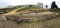
Six Rivers Charter High School (abbrev. Six Rivers) in Arcata, California has a garden and outdoor learning space located at the bottom of a hill below the main classrooms. The staircase originally connecting the space to the rest of the school had fallen deep into disrepair and sorely needed to be replaced this year (Fall 2019). The team spent a few weeks researching pathway and stair design, slope stabilization, retaining walls, pathway construction, erosion control, and native plants before meeting with Six Rivers' Principal Ron Perry to establish their personal criteria for the design. The team was tasked with designing a pathway that is safe, wheelbarrow accessible, widely plantable, cost effective, ecologically sound and aesthetically pleasing. The primary objective of our design was on functionality and durability. | |||
PDF - Full report of [https://www.appropedia.org/File:AZDC_215SRCHSPATHWAY_F19.pdf SRCHS pathway project] | |||
<gallery title="Before Construction"> | |||
File:AZDC building ORIGINALSTAIRCASE.jpg|Original staircase (Sept. 2019). | |||
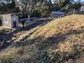
File:AZDC building PREWORKHILLSIDEFRONTVIEW.jpg|East facing perspective from tool shed (Sept. 2019). | |||
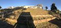
File:AZDC building SWITCHBACKPREWORK.jpg|View from switchback (Sept. 2019). | |||
</gallery> | |||
== Problem Statement and Criteria == | == Problem Statement and Criteria == | ||
The top priorities for any trail/pathway are safety and accessibility, and the importance of other criteria is situation specific. | |||
{| class="wikitable | [[File:AZDCfinalTireWall.PNG|thumb]] | ||
The top priorities for any trail/pathway are safety and accessibility, and the importance of other criteria is situation specific. For this project labor intensity and cost are very important because without prioritizing these the project may not have been able to reach completion in time. Remaining criteria is valued with respect to education. | |||
{| class="wikitable" | |||
! Criteria | ! Criteria | ||
! Weight (out of 10) | ! Weight (out of 10) | ||
| Line 60: | Line 54: | ||
|} | |} | ||
==Prototyping== | == Prototyping == | ||
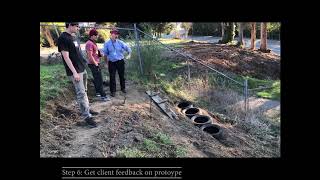
The first prototype was constructed out of drywall compound, chicken wire, and magazines on a plywood frame. The clam-shell cement blocks are represented by the colorful foam blocks, the urbanite retaining wall is represented by the black foam blocks, and the compact earth tire wall is represented by the slices of wine cork. The first problem posed was the sharp inside angle of the switchback. The fact that this would present an issue was confirmed by the second prototype which involved carving into the construction site. As a result of the prototyping process, the team chose to extend the landing section of the trail farther back into the hillside to allow for a gentler inside angle on the switchback. The prototype was tested by showing it to Cal Poly Humboldt engineering students who gave their opinions of what could be improved on and what could be potentially problematic or unsafe. | |||
<gallery title="First and Second Prototypes"> | |||
File:LabledProto.PNG|'''First Prototype''': Prototype with labels to aid in getting feed back from stake holders and experts. | |||
File:AZDC building Prototype2.png.JPG|'''First Physical Prototype''': Image of the first cuts into the hillside at Six Rivers. | |||
</gallery> | |||
== Description of Final Design == | |||
== | === Final Design === | ||
The final design shown below addresses the client criteria and insight gained through the prototyping process. The full length of the pathway is approximately 90' and the area of the landing is approximately 35 square feet. The bottom of the pathway to the landing is supported by a 66' urbanite retaining wall that expands upon a pre-existing concrete block retaining wall. The landing is supported by a compact earth tire retaining wall measuring approximately 54" high by 13' wide, and comprised of 24 tires arranged hexagonally. The portion of the pathway between the top and the landing does not require reinforcement. The pathway surface is composed of three layers: tamped earth as the base, a mixture of sand and gravel in the middle, and mulch on top. Outsloping of the pathway and Coweeta dips were used for drainage, and a combination of ripraps, straw, and grass seed were utilized as temporary erosion control for remaining bare slopes. All elements of the design were produced as planned to the satisfaction of the team as well as the client. | |||
The final design shown below addresses the client criteria and insight gained through the prototyping process. | |||
<gallery> | |||
File:AZDC FInal Trail1.jpg|'''Garden Pathway''': Landing at the switchback. | |||
File:AZDC Final Trail2.jpg|'''Final Trail''': Close up of the retaining wall structures and pathway. | |||
File:AZDC Final Trail3.jpg|'''Final Trail''': Overview of the final trail. | |||
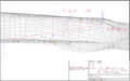
File:AZDC WhiteCAD.PNG|AutoCAD rendering of final design placement and dimensions (top view). | |||
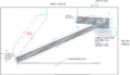
File:AZDC AlvaCAD.PNG|AutoCAD rendering of final design placement and dimensions (east facing view). | |||
</gallery> | |||
=== Costs === | === Costs === | ||
{| class="wikitable | |||
! Quantity | {| class="wikitable" | ||
! Quantity | |||
! Material or Service | |||
! Source | |||
! Cost ($) | |||
|- | |- | ||
| As needed | | As needed | ||
| Materials Transportation | |||
| Father of Dustin | |||
| 46.91 | |||
|- | |- | ||
| 1 | | 1 | ||
| | | Hay Bale | ||
| | | Three G's Hay and Grain | ||
| 8.62 | |||
|- | |- | ||
| | | 1 bag | ||
| Grass Seed | |||
| Mad River Gardens | |||
| 3.76 | |||
| | |||
| | |||
| | |||
|- | |- | ||
|-class="sortbottom" | | As needed | ||
| Recycled Concrete | |||
| Donated by: Figas Construction | |||
| 0 | |||
|- | |||
| As needed | |||
| Tires | |||
| Donated by: Anonymous | |||
| 0 | |||
|- | |||
| 1 cubic meter | |||
| Wood Chips | |||
| Free pile located at the Indianola Cuttoff | |||
| 0 | |||
|- class="sortbottom" | |||
! colspan="3"|Total Cost | |||
! 59.29 | |||
|} | |} | ||
==How to build== | == How to build == | ||
=== Compact Earth Tire Retaining Wall === | === Compact Earth Tire Retaining Wall === | ||
{{Step | |||
| number = 1 | |||
| text = [[File:AZDC building SOURCINGURBANITE.JPG|thumb]]Determine how many tires will be required for the wall by measuring the diameter and height of the tires to be built with. Then measure the height and width of the wall to be built and calculate how many tires will need to be in each row. This will determine the width and depth of the foundation. | |||
| image = AbdulKhalikKamaalACAD3.PNG | |||
}} | }} | ||
{{ | {{Step | ||
| number = 2 | |||
| text = Prepare the wall site by leveling and tamping down the soil where the first row of tires will be placed. | |||
| image = AZDC building FIRST ROW.PNG | |||
}} | |||
{{Step | |||
| number = 3 | |||
| text = Place the first row of tires neatly in a line and use a level to flatten them as evenly as possible. Place cardboard inside tire to cover the bottom hole. This prevents dirt from spilling out through the bottom as it is filled. The photo to the left demonstrates measuring the cardboard to be cut before it is inserted into the tire. | |||
| image = AZDCtireWallCardboard.PNG | |||
}} | |||
{{Step | |||
| number = 4 | |||
| text = Pack the first row! It is most efficient to have one person shoveling scoops of earth into the tire while one person packs it using a tamper, sledge hammer, or similar tool. If the local soil is particularly dry it is best to lightly dampen the soil to help it bind to itself.<br>'''Note 1''': Minimize plant/organic matter from mixing into the soil. Organic matter will decompose over time and this can cause the fill to shrink which could compromise the strength of the tire.<br>'''Note 2''': Be sure to pack in the sides of the tire. As you fill the tire it will be come increasingly difficult to compact the sides so a handheld sledge is recommended for this. | |||
| image = AZDCtireWall.PNG | |||
}} | }} | ||
{{Step | |||
| number = 5 | |||
| text = Place the second row of tires, staggering them such that they line up as in the photos for steps 5 and 6, and leveling them to be flat. | |||
| image = File:AZDC building TIREROW2.2.PNG | |||
}} | }} | ||
{{Step | |||
| number = 6 | |||
| image = AZDC building TIREROW2.PNG | |||
}} | |||
{{Step | |||
| number = 7 | |||
| text = Fill the second row by repeating steps 3 and 4. | |||
}} | |||
{{Step | |||
| number = 8 | |||
| text = Repeat the steps taken to produce the second row of tires and repeat until the final row has been finished. | |||
| image = AZDCtireWallConstructions.PNG | |||
}} | |||
{{Step | |||
| number = 9 | |||
| text = '''Optional''': Use your tires as planters by shallowly digging into them. The tires function well as planters and roots will add additional strength, but digging too deeply into them can compromise the strength of the soil that has been packed in. Placing above ground bottomless planters on the center hole of a tire is the recommended method. | |||
| image = AZDCfinalTireWall.PNG | |||
}} | }} | ||
=== Urbanite Retaining Wall === | === Urbanite Retaining Wall === | ||
The urbanite retaining wall described below is constructed from recycled concrete. Pieces of concrete with one flat side such as those sourced from old sidewalk are ideal, but not critical. This type of retaining wall is known as a gravity wall because it does not have anything anchoring the wall to solid ground. The strength and stability of this design is rooted in it's sheer weight, so it is important to remember that the sum mass of urbanite used is proportionate to the overall strength of the wall. | |||
{{Step | |||
| number = 1 | |||
| text = Determine where your retaining wall will lay and mark it's path with string. | |||
| image = AZDCwallRope.PNG | |||
}} | |||
{{Step | |||
| number = 2 | |||
| text = Create a foundation layer by digging out all loose dirt, tamping firm the earth that your first layer of urbanite will be placed on, and level it. | |||
}} | }} | ||
{{Step | |||
| number = 3 | |||
| text = Starting at one end of your wall set one block at a time choosing the heaviest pieces. Using the heaviest pieces on the bottom layer will give the greatest structural integrity. | |||
| image = AZDC building SOURCINGURBANITE.JPG | |||
}} | }} | ||
{{Step | |||
| number = 4 | |||
| text = Moving along the string, set another piece of urbanite next to the first piece, nestling them together such that the edges "lock" into place. | |||
| image = AZDC Building.gif | |||
}} | |||
{{Step | |||
| number = 5 | |||
| text = Fill in gaps between the blocks using a combination of soil and gravel. Massage the fill into place using tools before packing it in firmly so that fill can reach the most inner spaces. | |||
| image = AZDC building URBANITEROW1.PNG | |||
}} | |||
{{Step | |||
| number = 6 | |||
| text = Repeat steps 4 and 5 until the first layer is complete.<br>'''Note''': It is highly recommended that each block be firmly stabilized before moving on to subsequent blocks, rather than completing the entire row and returning to check stability of individual blocks afterwards. Check each block's stability by tapping it with your foot. If it wiggles in place then it has not been set firmly enough and must either have additional side/backfilling, or increased lateral support by adjusting the placement of adjacent blocks. This is difficult to do once the entire row is complete because adjusting the placement of any one piece will alter the placement of the blocks touching the one being adjusted. | |||
}} | |||
{{Step | |||
| number = 7 | |||
| text = Once the first row is firmly placed and stabilized, place the second row just as you did in steps 4 and 5. Use the heaviest blocks available. | |||
| image = AZDCheavyBlocks.PNG | |||
}} | |||
{{Step | |||
| number = 8 | |||
| text = Create as many rows as your project calls for, always checking for and addressing points of instability.<br>'''Note''': Optional measures for additional securing of blocks such mortar, cobb filler, and newly poured cement can be used, but are not critical to the structure. | |||
| image = AZDCretWallFinal.PNG | |||
}} | }} | ||
=== Trail Placement === | === Trail Placement === | ||
{{Step | |||
| number = 1 | |||
| text = Sketch potential layouts. | |||
| image = AZDC building TRAILPLACEMENT.JPG | |||
}} | }} | ||
{{Step | |||
| number = 2 | |||
| text = Layout trail with string and / or ruff digging. | |||
| image = AZDC Layout pic.PNG | |||
}} | |||
{{Step | |||
| number = 3 | |||
| text = Formalize layout. | |||
| image = AZDC HelliwellCAD.PNG | |||
}} | }} | ||
=== Path Surface === | === Path Surface === | ||
{{ | |||
{{Step | |||
| number = 1 | |||
| text = Armor the trail with a hard material such as gravel. | |||
| image = File:AZDC Gravel.PNG | |||
| caption = Backpack frame bike trailer | |||
}} | |||
{{Step | |||
| number = 2 | |||
| text = Tamp any loose material to add strength to trail surface. | |||
| image = File:AZDC Tamping.PNG | |||
| caption = Aleiha's parabolic solar cooker | |||
}} | |||
{{Step | |||
| number = 3 | |||
| text = Provide an easy walking surface such as wood chips. | |||
| image = File:AZDC Chips.PNG | |||
| caption = Important info | |||
}} | }} | ||
== Maintenance == | == Maintenance == | ||
This section details the known and anticipated maintenance that this design will require to remain functional and cosmetically intact. | This section details the known and anticipated maintenance that this design will require to remain functional and cosmetically intact. It is designed with the intent of being maintained by the students alone. | ||
=== Schedule === | === Schedule === | ||
;Daily | ;Daily | ||
*Plant care: watering and fertilizing as needed. | |||
* Plant care: watering and fertilizing as needed. | |||
;Weekly | ;Weekly | ||
*Remove dirt knocked onto pathway by gophers, pathway users, etc. | |||
* Remove dirt knocked onto pathway by gophers, pathway users, etc. | |||
;Yearly | ;Yearly | ||
*Analyze retaining walls for points of soil erosion that could affect the long term stability of the supporting structure. | |||
* Analyze retaining walls for points of soil erosion that could affect the long term stability of the supporting structure. | |||
;As necessary | ;As necessary | ||
*Add mulch or gravel to the top layer of the pathway at points where it has become muddy or uneven. | |||
* Add mulch or gravel to the top layer of the pathway at points where it has become muddy or uneven. | |||
== Suggestions for future changes == | == Suggestions for future changes == | ||
| Line 257: | Line 294: | ||
Team AZDC recommends the following as future changes to the project: | Team AZDC recommends the following as future changes to the project: | ||
*A handrail placed on the west side of the path running from the landing to the bottom. | * A handrail placed on the west side of the path running from the landing to the bottom. | ||
*Planting an assortment of edible fruiting plants that would also serve as additional slope stabilization such as: | * Planting an assortment of edible fruiting plants that would also serve as additional slope stabilization such as: | ||
** Snow Berries | |||
** Goumi Berries | |||
** Huckleberries | |||
** Elderberries | |||
** Chilean Guava | |||
*A cob bench embedded into the uphill side of the landing to provide additional slope stabilization as well as an aesthetic and practical feature. | * A cob bench embedded into the uphill side of the landing to provide additional slope stabilization as well as an aesthetic and practical feature. | ||
* A roof for the cob bench so that it will survive the Humboldt county winter. | |||
== About the Team == | |||
Environmental Resource Engineering students at Cal Poly Humboldt, Fall 2019. | |||
[[File:AZDCteamPic.PNG|thumb|none|Connor White, Dustin Helliwell, Zachary Alva, Abdul Khalik Kamaal]] | |||
== Video == | |||
{{Video|io1jp1NSxpo}} | |||
{{Page data | |||
| part-of = Engr205 Introduction to Design | |||
| keywords = garden, pathway, retaining wall, grass seeds, hay bale, recycled concrete, tires, Upcycling gallery | |||
| sdg = SDG11 Sustainable cities and communities | |||
| published = 2019 | |||
| organizations = Six Rivers Charter School, Engr205 Introduction to Design, Cal Poly Humboldt | |||
| license = CC-BY-SA-3.0 | |||
| language = en | |||
}} | |||
[[Category:Engr205 Introduction to Design]] | |||
[[Category:Six Rivers Charter School]] | |||
[[Category:Gardening]] | |||
[[Category:Upcycling]] | |||
[[Category:Garden]] | |||
Latest revision as of 14:44, 28 February 2024

Six Rivers Charter High School (abbrev. Six Rivers) in Arcata, California has a garden and outdoor learning space located at the bottom of a hill below the main classrooms. The staircase originally connecting the space to the rest of the school had fallen deep into disrepair and sorely needed to be replaced this year (Fall 2019). The team spent a few weeks researching pathway and stair design, slope stabilization, retaining walls, pathway construction, erosion control, and native plants before meeting with Six Rivers' Principal Ron Perry to establish their personal criteria for the design. The team was tasked with designing a pathway that is safe, wheelbarrow accessible, widely plantable, cost effective, ecologically sound and aesthetically pleasing. The primary objective of our design was on functionality and durability.
PDF - Full report of SRCHS pathway project
-
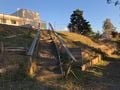
Original staircase (Sept. 2019).
-
East facing perspective from tool shed (Sept. 2019).
-
View from switchback (Sept. 2019).


Problem Statement and Criteria[edit | edit source]

The top priorities for any trail/pathway are safety and accessibility, and the importance of other criteria is situation specific. For this project labor intensity and cost are very important because without prioritizing these the project may not have been able to reach completion in time. Remaining criteria is valued with respect to education.
| Criteria | Weight (out of 10) |
|---|---|
| Safety and Accessibility | 10 |
| Labor Intensity | 9 |
| Cost | 7 |
| Plantability | 7 |
| Ecology | 6 |
| Maintenance | 5 |
| Educational Value | 4 |
| Aesthetic | 4 |
Prototyping[edit | edit source]
The first prototype was constructed out of drywall compound, chicken wire, and magazines on a plywood frame. The clam-shell cement blocks are represented by the colorful foam blocks, the urbanite retaining wall is represented by the black foam blocks, and the compact earth tire wall is represented by the slices of wine cork. The first problem posed was the sharp inside angle of the switchback. The fact that this would present an issue was confirmed by the second prototype which involved carving into the construction site. As a result of the prototyping process, the team chose to extend the landing section of the trail farther back into the hillside to allow for a gentler inside angle on the switchback. The prototype was tested by showing it to Cal Poly Humboldt engineering students who gave their opinions of what could be improved on and what could be potentially problematic or unsafe.
-
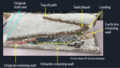
First Prototype: Prototype with labels to aid in getting feed back from stake holders and experts.
-
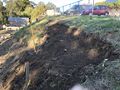
First Physical Prototype: Image of the first cuts into the hillside at Six Rivers.


Description of Final Design[edit | edit source]
Final Design[edit | edit source]
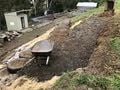
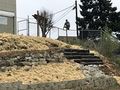
The final design shown below addresses the client criteria and insight gained through the prototyping process. The full length of the pathway is approximately 90' and the area of the landing is approximately 35 square feet. The bottom of the pathway to the landing is supported by a 66' urbanite retaining wall that expands upon a pre-existing concrete block retaining wall. The landing is supported by a compact earth tire retaining wall measuring approximately 54" high by 13' wide, and comprised of 24 tires arranged hexagonally. The portion of the pathway between the top and the landing does not require reinforcement. The pathway surface is composed of three layers: tamped earth as the base, a mixture of sand and gravel in the middle, and mulch on top. Outsloping of the pathway and Coweeta dips were used for drainage, and a combination of ripraps, straw, and grass seed were utilized as temporary erosion control for remaining bare slopes. All elements of the design were produced as planned to the satisfaction of the team as well as the client.
-
Garden Pathway: Landing at the switchback.
-
Final Trail: Close up of the retaining wall structures and pathway.
-
Final Trail: Overview of the final trail.
-
AutoCAD rendering of final design placement and dimensions (top view).
-
AutoCAD rendering of final design placement and dimensions (east facing view).


Costs[edit | edit source]
| Quantity | Material or Service | Source | Cost ($) |
|---|---|---|---|
| As needed | Materials Transportation | Father of Dustin | 46.91 |
| 1 | Hay Bale | Three G's Hay and Grain | 8.62 |
| 1 bag | Grass Seed | Mad River Gardens | 3.76 |
| As needed | Recycled Concrete | Donated by: Figas Construction | 0 |
| As needed | Tires | Donated by: Anonymous | 0 |
| 1 cubic meter | Wood Chips | Free pile located at the Indianola Cuttoff | 0 |
| Total Cost | 59.29 | ||
How to build[edit | edit source]
Compact Earth Tire Retaining Wall[edit | edit source]


Prepare the wall site by leveling and tamping down the soil where the first row of tires will be placed.

Place the first row of tires neatly in a line and use a level to flatten them as evenly as possible. Place cardboard inside tire to cover the bottom hole. This prevents dirt from spilling out through the bottom as it is filled. The photo to the left demonstrates measuring the cardboard to be cut before it is inserted into the tire.

Pack the first row! It is most efficient to have one person shoveling scoops of earth into the tire while one person packs it using a tamper, sledge hammer, or similar tool. If the local soil is particularly dry it is best to lightly dampen the soil to help it bind to itself.
Note 1: Minimize plant/organic matter from mixing into the soil. Organic matter will decompose over time and this can cause the fill to shrink which could compromise the strength of the tire.
Note 2: Be sure to pack in the sides of the tire. As you fill the tire it will be come increasingly difficult to compact the sides so a handheld sledge is recommended for this.

Place the second row of tires, staggering them such that they line up as in the photos for steps 5 and 6, and leveling them to be flat.

Fill the second row by repeating steps 3 and 4.

Repeat the steps taken to produce the second row of tires and repeat until the final row has been finished.
Optional: Use your tires as planters by shallowly digging into them. The tires function well as planters and roots will add additional strength, but digging too deeply into them can compromise the strength of the soil that has been packed in. Placing above ground bottomless planters on the center hole of a tire is the recommended method.
Urbanite Retaining Wall[edit | edit source]
The urbanite retaining wall described below is constructed from recycled concrete. Pieces of concrete with one flat side such as those sourced from old sidewalk are ideal, but not critical. This type of retaining wall is known as a gravity wall because it does not have anything anchoring the wall to solid ground. The strength and stability of this design is rooted in it's sheer weight, so it is important to remember that the sum mass of urbanite used is proportionate to the overall strength of the wall.

Determine where your retaining wall will lay and mark it's path with string.
Create a foundation layer by digging out all loose dirt, tamping firm the earth that your first layer of urbanite will be placed on, and level it.
Starting at one end of your wall set one block at a time choosing the heaviest pieces. Using the heaviest pieces on the bottom layer will give the greatest structural integrity.

Moving along the string, set another piece of urbanite next to the first piece, nestling them together such that the edges "lock" into place.

Fill in gaps between the blocks using a combination of soil and gravel. Massage the fill into place using tools before packing it in firmly so that fill can reach the most inner spaces.
Repeat steps 4 and 5 until the first layer is complete.
Note: It is highly recommended that each block be firmly stabilized before moving on to subsequent blocks, rather than completing the entire row and returning to check stability of individual blocks afterwards. Check each block's stability by tapping it with your foot. If it wiggles in place then it has not been set firmly enough and must either have additional side/backfilling, or increased lateral support by adjusting the placement of adjacent blocks. This is difficult to do once the entire row is complete because adjusting the placement of any one piece will alter the placement of the blocks touching the one being adjusted.

Once the first row is firmly placed and stabilized, place the second row just as you did in steps 4 and 5. Use the heaviest blocks available.

Create as many rows as your project calls for, always checking for and addressing points of instability.
Note: Optional measures for additional securing of blocks such mortar, cobb filler, and newly poured cement can be used, but are not critical to the structure.
Trail Placement[edit | edit source]

Sketch potential layouts.

Layout trail with string and / or ruff digging.

Formalize layout.
Path Surface[edit | edit source]

Armor the trail with a hard material such as gravel.

Tamp any loose material to add strength to trail surface.

Provide an easy walking surface such as wood chips.
Maintenance[edit | edit source]
This section details the known and anticipated maintenance that this design will require to remain functional and cosmetically intact. It is designed with the intent of being maintained by the students alone.
Schedule[edit | edit source]
- Daily
- Plant care: watering and fertilizing as needed.
- Weekly
- Remove dirt knocked onto pathway by gophers, pathway users, etc.
- Yearly
- Analyze retaining walls for points of soil erosion that could affect the long term stability of the supporting structure.
- As necessary
- Add mulch or gravel to the top layer of the pathway at points where it has become muddy or uneven.
Suggestions for future changes[edit | edit source]
Team AZDC recommends the following as future changes to the project:
- A handrail placed on the west side of the path running from the landing to the bottom.
- Planting an assortment of edible fruiting plants that would also serve as additional slope stabilization such as:
- Snow Berries
- Goumi Berries
- Huckleberries
- Elderberries
- Chilean Guava
- A cob bench embedded into the uphill side of the landing to provide additional slope stabilization as well as an aesthetic and practical feature.
- A roof for the cob bench so that it will survive the Humboldt county winter.
About the Team[edit | edit source]
Environmental Resource Engineering students at Cal Poly Humboldt, Fall 2019.