Tardigrade (talk | contribs) |
Anonymous1 (talk | contribs) |
||
| Line 27: | Line 27: | ||
==Base construction== | ==Base construction== | ||
The base is made of four pieces of lumber: A1, A2, B1, and B2 as shown in Figure 5-5. | The base is made of four pieces of lumber: A1, A2, B1, and B2 as shown in Figure 5-5. | ||
The two main pieces you will be building here are mirrored. When a picture of a specific side is shown the piece numbers usually are | The two main pieces you will be building here are mirrored. When a picture of a specific side is shown, the piece numbers usually are grouped (ex. A1 goes with B1, or A2 with B2, etc.). The B piece is placed flush with one end of the A piece. Once flush, place the C pieces flush to the A beam lengthwise and flush to the end of the B beam as seen in Figure 5-6, 5-7, and 5-8. Secure the C pieces to the AB pieces with six screws as shown in Figure 5-8. | ||
Next you will want to take piece D3 and hold it upright perfectly flush with pieces C and A as shown in Figure 5-9. Once piece D3 is flush, put piece D1/D2 flush on top of piece C as shown in Figure 5-10. | Next you will want to take piece D3 and hold it upright perfectly flush with pieces C and A as shown in Figure 5-9. Once piece D3 is flush, put piece D1/D2 flush on top of piece C as shown in Figure 5-10. | ||
Now secure screws from D into C three or more times along the length D as shown in Figure 5-11. | Now secure screws from D into C three or more times along the length D as shown in Figure 5-11. | ||
Revision as of 15:55, 12 July 2011
Construction Materials
Wood-
-(1) Six inches by one inch by six feet *( 5 ½” x ¾” x 72” )*
-(1) Six inches by one inch by six to seven inches *(5 ½” x ¾” x (6” to 7”))* This piece can vary in size as long as it is large enough to cover the rear of the pulley compartment.
-(2) Four inches by four inches by six feet *( 3 ½” x 3 ½” x 72” )*
-(2) Four inches by four inches by four feet *( 3 ½” x 3 ½” x 72” )*
-(2) Half inch by six inches by four feet. These pieces are made of half inch thick plywood.
-(2) Two feet by two feet. These pieces are made of half inch thick plywood.
-(3) Four inches by four inches by five and a half inches *(3 ½” x 3 ½” x 5 ½”)*
-(3) Base supports: long enough to span the width of the rowing machine blender
-(4) Six inches by one inch by four feet *( 5 ½” x ¾” x 48” )*
Hardware-
-(2) S-hooks
-(4) Bolts
- Lots of nails, screws, nuts, and bolts
Bicycle-
-(1) Bicycle rack
-(1) Bicycle wheel & tire
-(2) Derailleur cogs
-(2) Pulleys
-(2) Master links
-(3) One speed bicycle chains
Base construction
The base is made of four pieces of lumber: A1, A2, B1, and B2 as shown in Figure 5-5. The two main pieces you will be building here are mirrored. When a picture of a specific side is shown, the piece numbers usually are grouped (ex. A1 goes with B1, or A2 with B2, etc.). The B piece is placed flush with one end of the A piece. Once flush, place the C pieces flush to the A beam lengthwise and flush to the end of the B beam as seen in Figure 5-6, 5-7, and 5-8. Secure the C pieces to the AB pieces with six screws as shown in Figure 5-8. Next you will want to take piece D3 and hold it upright perfectly flush with pieces C and A as shown in Figure 5-9. Once piece D3 is flush, put piece D1/D2 flush on top of piece C as shown in Figure 5-10. Now secure screws from D into C three or more times along the length D as shown in Figure 5-11. Once both base pieces 1 and 2 are finished (compare both of your base pieces to Figures 5-12, 5-13, and 5-14) put them top side down facing each other as shown. Place D3 on top of D1 and D2 and press base piece 1 and 2 together. See Figure 5-15, 5-16, and 5-17. Now D3 can be nailed into D1 and D2 using carpenter nails. See Figure 5-18 and 5-19. Next take E and secure it flush with D3, which is the rear of the base. Seen Figure 5-20 and 5-21. Next you will make the base supports out of a piece of wood. The dimensions of this wood can vary but should be around five feet by two inches by two inches. Cut the piece of wood into three parts lengthwise. Screw these pieces flush to both ends and in the very center of the base. These secure the base beams together. See Figure 5-22. Once secured flip whole base over.
-
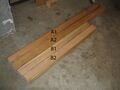
Figure 5-5: Wooden base beams
-
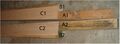
Figure 5-6
-
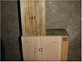
Figure 5-7
-
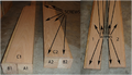
Figure 5-8
-
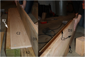
Figure 5-9
-
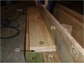
Figure 5-10
-
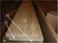
Figure 5-11
-
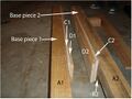
Figure 5-12
-
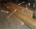
Figure 5-13
-
Figure 5-14
-
Figure 5-15
-
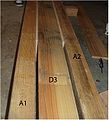
Figure 5-16
-
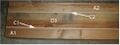
Figure 5-17
-
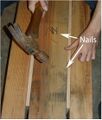
Figure 5-18
-
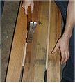
Figure 5-19
-
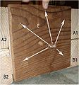
Figure 5-20
-
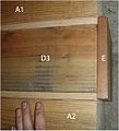
Figure 5-21
-
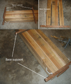
Figure 5-22


Pulley Compartment
The chain and pulley system in the pulley compartment requires:
- 3 bike chains
- 2 bicycle chain master links
- 2 pulleys
- 2 springs
- 2 threaded hooks
- 2 fastening links
- and a bicycle derailleur.
Each pulley is taken apart, and a pulley wheel from a bicycle derailleur replaced the original wheel of the pulley. It is better to use a derailleur pulley, such as the one seen in Figure 5-9, that is larger in size that is approximately the same diameter as the original pulley wheel seen in Figure 5-10. This is an optional and is not required. This was done to mesh with the chain, quiet the system down, and satisfy the added value criteria. To prepare the chain for the pulley system, it requires three single speed bicycle chains to be connected using a bicycle chain master links as seen in Figure 5-11. The master link has three parts, the master link, plate, and clip. The master link is inserted into the end of the chain, the plate placed onto the master link on the other side of the chain, and then secured with the supplied clip. Each pulley has a spring attached to it by a fastening loop that resembles a small binary with a threaded gate as seen in Figure 5-12. The springs are attached to hooks threaded into the anterior and posterior of the pulley compartment. The distance between the hooks can vary as long as the single hook threaded into the anterior of the pulley compartment is approximately equal to the half the distance between the two hook screws threaded into the opposite end as seen in Figure 5-13 and Figure 5-14. One spring is attached to the top hook at the posterior end and the other pulley and spring is attached to the hook at the anterior end of the pulley compartment as seen in Figures 5-15 and 5-16. The chain is routed into the pulley system and through the top pulley at the posterior end, then through the anterior pulley, and anchored to the bottom hook at the posterior end using another master link provided with the bicycle chains also shown in Figure 5-16. The complete chain and pulley system profile will resemble an “S” shape as seen in Figure 5-17.
-
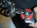
Figure 5-9: Bicycle derailleur with large red pulley
-
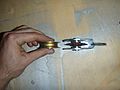
Figure 5-10: Pulley with bicycle derailleur pulley wheel
-
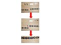
Figure 5 11: Master link installation sequence
-
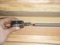
Figure 5-12: This figure needs an updated photo with the attachment
-
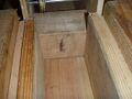
Figure 5-13: Anterior hook placement inside the pulley compartment
-
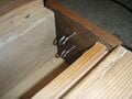
Figure 5-14: Posterior hook placement inside pulley compartment
-
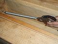
Figure 5-15: Spring attachment at anterior end of the pulley compartment NEEDS CURRENT PHOTO
-
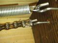
Figure 5-16: Spring and chain attachment at posterior end of the pulley compartment
-
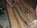
Figure 5-17: Complete Pulley system with chain routed. Posterior of pulley compartment in foreground.


Wheel Mount
Take pieces H1 and H2 and put them on top of each other. Drill holes large enough to fit a seven inch long bolt through in the spots shown in Figure 5-23, 5-24, and 5-25. Now take bolt piece F between H1 and H2 at holes A and B. See Figure 5-24 and 5-26. Take the pulley wheel out of the pulley and place it on the mount bolts. See Figure 5-27. Put the bolts with wheels through holds C and D as in Figure 5-24. Secure the bolts through all the holes and you should have a mount like Figure 5-28. Now take the mount and put it in the spaces alongside pieces A1 and A2 as in Figure 5-29. Take the third F piece and wedge it against the ends of the pulley compartment as shown in Figure 5-29. Take a hook and screw it into the wedged F piece as this hook will be used to secure the pulley system. See Figure 5-30. Now take four L brackets and secure the Mount to the Base. The bottom of the Mount should not touch the floor and should be flush with the bottom of the Base. See Figure 5-31.
-
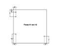
Figure 5-23
-
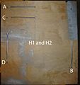
Figure 5-24
-
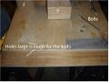
Figure 5-25
-
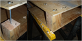
Figure 5-26
-
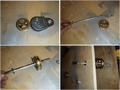
Figure 5-27
-
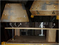
Figure 5-28
-
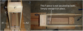
Figure 5-29
-
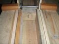
Figure 5-30
-
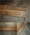
Figure 5-31


Blender Mount
The blender platform construction depends on the blender interface so start with the blender interface. Once the interface has been constructed, you can make more accurate measurements to erect the blender platform. This design uses a rear cargo rack intended for a bicycle. That rack used in this design does not have a flat surface on top. An example can be seen in Figure 5-22. The chosen board to be installed on the rack can vary. It just has to be thick enough for wood screws that secure the hub to sink into. Cut this board so that it is approximately the area of the top of the rack. There are mounting holes on the rack to attach to a bicycle toward the front of the rack. Use these holes to attach the board. Mark where the holes are onto the wood from the bottom and drill into the wood. Use nuts and bolts that fit the hole and are long enough to go through the rack and the board to fasten the board to the rack. At the other end of the rack, a piece of strap steel with a hole at each end is stretched over the member that runs perpendicular to the bicycle wheel so that a hole on the strap steel is on each side of this member. Mark these holes onto the bottom of the board to drill holes and secure the board further with nuts and bolts. A strap that is used to fasten bicycle racks to a bicycle frame works well for this application. Next is securing the blender interface made with the bicycle hub to the board that has been mounted onto the rack. It is very important that you choose the correct side of the wheel to measure from. You want your blender coupling to rotate in the direction of the square edge of the splines on the coupling seen in Figure 5-23. In this case, the blender interface is mounted on the drive side of the wheel. Approximate where the rack needs to be positioned on the wheel mount by holding the hub up to the board so the top flange of the hub is flush with the top of the board as shown in Figure 5-24. It is very important that the skateboard wheel strikes the bicycle tire at the top center of the tire as close to directly above the axle as possible. Once this has been determined, mark where the holes of the rack are on the wheel mount. Once the holes are drilled, install the rack/blender platform onto the wheel mount with nuts, bolts, and washers and be sure that the blender platform is level. Once this is mounted, re locate the spot on the blender platform where the skateboard wheel strikes the top, center, and midline of the bicycle tire and outline the hub onto the side of the board as seen in Figure 5-25.
Cut a slot where you have marked the board so that the flange of the hub is flush to the top of the board and so there is enough wood to secure the hub onto with wood screws as seen in Figure 5-26. Cut the slot deep enough so the skateboard wheel is positioned against the wheel with a considerable amount of pressure to optimize friction. Fasten the hub onto the board using adequate wood screws that sink far enough into the board. Use the holes in the hub flange to do this. You may have to drill out the holes in the flange to get a wood screw through. Arrange the screws in as much of a square that the amount of wood to screw into allows.
To make the blender mount, three pieces of scrap wood was used. First, the blender is placed on top of the coupling and the distance between the base of the blender and the wooden deck is measured. These three pieces were cut to that height and they are all equal in length. These three equal pieces make ¾ of a square and were glued together. They were then glued to the platform deck so the coupling is in the center as seen in Figure 5-27. All three pieces of wood should support part of the blender base.
To secure this platform further, miniature L brackets are installed on the outside of each piece of wood as shown in Figure 5-28. Velcro is used to secure the blender during operation so the top outer rim of this blender platform is lined with Velcro. A circle is traced around the blender base to indicate where the blender needs to be placed on the mount.
The final step to complete the blender platform is to install a supporting strut. A large wooden dowel resembling a closet coat rack is used in this application but any sufficient beam of wood will work. Keeping the platform level, the dowel extends flush from the end of the platform and extends flush onto the top right corner of the wheel mount when facing the row machine with the wheel on the left as shown in Figure 5-29 and is fastened with wood screws.
-
Figure 5-22: Bottom view of bicycle rack and blender platform
-
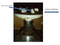
Figure 5-23: Spline close up to determine coupling rotation direction
-
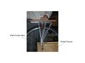
Figure 5-24: Demonstration of how to determine blender platform placement
-
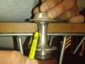
Figure 5-25: Marking where a slot will be cut into the blender platform
-
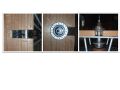
Figure 5-26: Different views of blender coupling installation
-
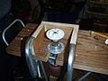
Figure 5-27: Blender mount precisely glued to platform deck
-
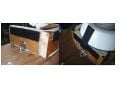
Figure 5-28: Blender platform with mini L brackets and Velcro installed
-
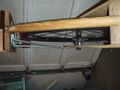
Figure 5-29: View of wooden support strut


Blender Drive Interface
The following operation for constructing your own friction drive blender interface is not a universal solution. As explain in the literature review, the various styles of blender couplings will determine the approach to take. This solution is one way to do it but will likely not come out exactly the way shown. A discarded, multiple speed freewheel, rear bicycle hub is used as the central component. A skateboard wheel is used as the friction roller. The blender coupling attached to the base of the blender is threaded off the drive shaft. This coupling is threaded on in reverse and is unthreaded in reverse. The coupling and the skateboard wheel are attached to the axle of the hub using a quick release skewer and a series of nuts and spacers. The diagram below in Figure 5-19 shows the order in which the described items are put together to create the blender drive interface. Figure 5-19 shows the components that need to be stacked on the skewer in order. First, the coupling needs to be drilled out for the skewer to pass through. Use a drill bit that is as close to the outer diameter of the skewer as possible. On the top side of the coupling, drill a larger shallow hole for a lock nut to sit flush in. This should look like the result shown in Figure 5-20. Depending on the skewer that is available, an unspecified amount of washers will need to be included in the stack of components on the skewer. It is important that the skewer does not protrude beyond the top of the lock nut as seen in Figure 5-20. Use enough spacers to achieve this. The end result of the friction drive blender interface should look like something similar to Figure 5-21.
-
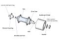
Figure 5-19: Blender interface with components in stacking order
-
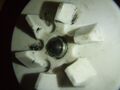
Figure 5-20: Top view of blender coupling with nylon lock nut
-
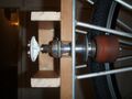
Figure 5-21: Friction Drive Interface


Rolling Seat
The seat was constructed using two pieces of wood and a set of skateboard trucks and longboard wheels. In this case, two pieces of wood were used to increase the strenth of the seat. To assemble the seat, first place the longboard wheels on the skateboard trucks and secure them using nuts. Next, turn the piece of wood so that it is top-side down and align the skateboard trucks on the bottom. The trucks must be parallel and centered to the width of the wood, one inch from the ends of the lenth and as in line with one another as possible. Once properly placed, take a pencil and outline the trucks and mark where the holes will be. These holes must then drilled and the trucks can be screwed in. While the orientation of trucks is important when actually being used on skateboards, it almost irrelevant when making this seat.
-
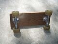
An image of the underside of the skateboard.
