Reprap is an open-source 3D printer, presently under community development. It is being designed to produce as many of it's own parts as possible, and hence self-replicate. This appropedia page describes the build process that Queen's Applied Sustainability Group is taking to build one, and contains a general build trajectory. Detailed documentation of each step is being filled in as the machine is built.
To Do List
- Build mendel boards for mounting electronics, printing board - look into laser, water cutting the boards out of various materials
- Solve SD card/extruder head diving problem
- Search on RapMan forum for solutions
- Possible - build mechanical blocker to prevent head damage
- Possible - build electronic watchdog that warns of head dive/shuts off machine (kill switch)
- Calibrate new RapMan extruder - looks good so far
Order a few more components from digikey, TTL-USB cable- Solder pins onto I2C connector on mobo before connecting to extruder
- Build opto-endstops
- Add molex connectors to stepper motors
- Build IDC cables (cable lengths are in brackets (cm) on this wiring diagram. The thick lines represent a connection with multiple wires, the bold numbers are the number of wires in these connections.
- Program and test electronics boards
- Continue calibrating RapMan and print mendel RP parts
- Cut threaded rods, other smaller non-RP mechanical tasks
Electrical Components Build and Test
BEFORE ANY CIRCUIT BOARDS ARE TAKEN OUT OF THEIR PACKAGING, TOUCH THE SINK FAUCET WITH BOTH HANDS TO GROUND YOURSELF AND GET RID OF ELECTROSTATIC CHARGE
If you are new to electronics, there is an excellent Beginners guide to electronics on the reprap wiki.
The wiring of all the components together is described on a circuit diagram here, and small mods required are described here. The instructions below are for GEN3 electronics (v1.2 motherboard, v2.2 extruder controller, v2.3 stepper driver). Gen3Elec
Making Additional Mods
The makerbot boards pre-fabbed for Cupcake work with RepRap with a few very small modifications. You can also modify them further to get rid of chunky RJ45 cabling, described here which links from here. It also discusses the minor adaptations needed to keep the boards more or less how they came. For our first RepRap, we are going to keep the boards how they came as much as possible; this is described here
Other links for editing the boards:
How to modify the power to not use an ATX power supply info: briefly mentioned here and here and described in more detail here.
How to install RepRap programming software on Windows
These instructions are meant to be an additional support to the ones on RepRap.org. Follow the instructions on the RepRap wiki. The instructions are also outlined in less detail here, with different links to download the install package (reprap-mendel-20100702.zip vs. reprap-gen3-firmware-1.2.zip). There may be discrepancies between the two *.zip sources, and the dated one (which has been used below as stated here) may be unstable. This needs to be sorted out.
- Get arduino-0018 (it doesnt "install" on windows) and unzip it to where you want it installed. It is now installed.
- Unzip sanguino-0018 and follow the directions in sanguiono.txt to copy the files into arduino.
- Start arduino.exe; select tools->board->sanguino. You are now set up with sanguino.
- Get java V 6; the website will tell you if you already have it installed.
- Set the user PATH environment variable manually for JAVA. instructions for Windows 7 here ensure there is a ; at the end, and no space at the beginning (before or after the ; ) or it wont work.
- Reboot to allow the PATH variable to update. If it doesnt work, try adding java to the admin PATH environment variable
- Get the RepRap software we may have to get an updated version, we presently have reprap-mendel-20100702.zip and unzip it to C:/Program Files/RepRap (you must use this default path, or the script files wont work)
- Run reprap.bat in the RepRap folder to ensure it is working. This did not work the first time for us due to no USB connection, but it should be able to find java. If it cant find java, your PATH variable has not been setup correctly.
- Close the RepRap program.
Now you're all set up to program your motherboard, and extruder controllers.
How to install the FiveD_GCode_Interpreter Mendel Code onto the RepRap (cupcake) motherboard


Make a USB<->serial & power cableActually, dont. We'll use an ATX (computer) power supply, which plugs into all the boards, and a separate USB-TTL cable.- Add two 2-pin headers to the I2C ports, described here, and add a two pin header and jumper next to the TTL programming port; headers are shown here at A and B. The motherboard is described here.
- Follow the directions here to install the FiveD_Gcode_interpreter RepRap code onto the motherboard alternatives here, check to make sure that FiveD can run a non-stepper extruder
- Copy configuration.h.dist, located in C:\Program Files\RepRap\mendel\firmware\FiveD_GCode\FiveD_GCode_Interpreter to a new file, named configuration.h in the same directory
- Run arduino.exe
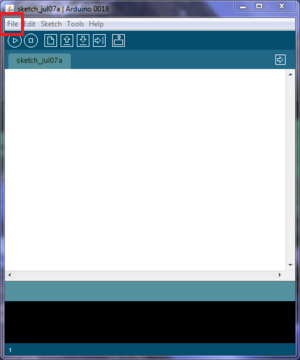
- Click File -> Open and navigate to C:\Program Files\RepRap\mendel\firmware\FiveD_GCode\FiveD_GCode_Interpreter. Select FiveD_GCode_Interpreter.pde
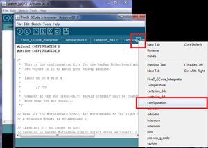
- Click the arrow to switch tabs; select configuration
- Read the file and make changes, or, for the Queen's machine use the file provided here configured to our machine File:Mendel-config-queens.odt. This is where you make settings for how the motors are running, and tell the firmware which kind of hardware you have.
- Click File->Save. If you get access denied error, this is because your user account does not have write permissions on configuration.h. Navigate to the folder immediately above configuration.h, right-click on the folder, select properties. Ensure "read-only" attribute is not set. Select Security -> User permissions -> Edit and ensure modify permissions are checked. Try again to save the file.
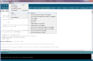
- Select Tools->Board->Sanguino then select Sketch->Verify/Compile.
- Continue following directions on how to upload the compiled code to the motherboard; the ATX power supply is required (I believe) as we are not modifying the motherboard to be USB powered.
- Test the motherboard, instructions here
How to install the Mendel Code onto the RepRap (cupcake) extruder controller board
- Ensure your motherboard has been tested (above)
- Check the info about the extruder boards here (make any cable connector changes: can swap out RJ45 for separate power, signal pins; we arent doing this).
- Follow the directions to install the RepRap code onto the extruder controller board. This is very similar to the motherboard program, described above. Be careful to make changes where necessary for the extruder board code, do not simply follow the same directions as for the motherboard.
- Copy configuration.h.dist, located in C:\Program Files\RepRap\mendel\firmware\FiveD_GCode\Extruder to a new file, named configuration.h in the same directory
- Run arduino.exe
- Click File -> Open and navigate to C:\Program Files\RepRap\mendel\firmware\FiveD_GCode\Extruder\. Select Extruder.pde
- Click the arrow to switch tabs; select configuration
- Read the file and make changes, or, for the Queen's machine use the file provided here configured to our machine File:Mendel-e-config-queens.odt. This is where you make settings for how the extruder motor runs, and tell the firmware which kind of hardware you have.
- Click File->Save. If you get access denied error, this is because your user account does not have write permissions on configuration.h. Navigate to the folder immediately above configuration.h, right-click on the folder, select properties. Ensure "read-only" attribute is not set. Select Security -> User permissions -> Edit and ensure modify permissions are checked. Try again to save the file.
- Click the arrow to switch tabs; select temperature.h.
- Ensure that the thermistor selected is correct for your thermistor. The model for Plastruder MK4 is a 100K Epcos NTC Thermistor, part number B57560G104F. Information on how to generate a custom temperature table to insert into temperature.h is available here; Type createTemperatureLookup.py -h for the help file of the thermistor script. Do not enter values for R1 or R2 as the default is fine (I believe these are used to calculate the actual current, ie including the effects of the output resistance of the ADC, though I am still looking for info)
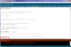
- Select Tools->Board->Arduino Diecimila or Duemilanove w/ ATmega 168 then select Sketch->Verify/Compile. It should have a Done Compiling message at the bottom when it has successfully compiled
- Continue following directions on how to upload the compiled code to the extruder controller
- Follow the instructions to check power, make a cable, and test the extruder communication with the motherboard
How to test the stepper motor drivers
- Ensure your motherboard has been tested (above)
- Put female molex connectors on the stepper motors, ensuring the correct order of wires here and here (or can swap out some connectors on the driver boards for the reprap versions, described here)
- Follow the stepper driver test instructions to build a cable, test power, and test the motor driver board communication with the motherboard
How to test the opto-switches
- Build your opto switches, we have makerbot ones which are described here, we're building the first set with RJ45 connectors.
- Ensure your motherboard and stepper drivers have been tested (above)
- Follow the optoswitch test instructions to build a cable, test power, and test the board communication with the motherboard
Assembly
After this is all tested, you should be ready to assemble the electronics onto the machine.
- Follow instructions to mount electronics (requires some Rapid Protoyped (RP) parts).
- Follow instructions to wire electronics.
Mechanical non-RP Build
Follow these instructions.
- Cut threaded rods to lengths *.ods given here
- Cut print bed and circuit mounting boards to size, *.ods given here, there is also duplicate information available somewhere on the RepRap.org site (needs to be compared to the *.ods). Kristen has some information compiled on alternative print beds
- Cut belts, build extruder background information here assembly instructions here, prepare studs, thin sheet
- Build, follow mechanical building instructions and build tips, and creating photographic build instructions (this is dependant on having RP'ed parts printed).
Instructions should be:
- universal language (pictures) with lots of arrows
- exploded assembly view of how to put together
- include parts list for each picture
- include method to differentiate between very similar parts (IKEA-esk)
Print RP parts
- Download *.stl files from the official site or user-submitted grouped part files from thingiverse 24 sheets one sheet, rearrange parts to print
- Convert to GCODE following directions on the 3D Model to G-Code File for Rapman protocol
- Print, following instructions on the Rapman protocol page
- Clean up parts
- Drill or file out bolt holes
- Remove plastic threads
- File uneven mating edges
- Acetone (test with one to see if quality difference is worth it)
Running RepRap
Once the machine is all assembled and tested separately, now we have to drive it with the computer.
We have the Gen3 Electronics, how to drive it is described here. A recommended driving software is ReplicatorG.
This page describes how to drive the machine with the Java RepRap.bat software, while this page is the least hardware intensive method. It is not clear which hardware electronics version they are meant to drive.
Alternative software
Boards for Reprap
Get all solid edge parts here:([1])
Motherboard plate
- place to mount extruder controller and motherboard
- made from MDF
- schematics
- solid edge file is located in this area in the downloaded files: reprap-mendel-20100308/mendel/mechanics/solid-models/Temporary/SolidEdge/circuit-boards motherboard-plate.par
Stepper motor mounting board:
- place to mount stepper motor drivers and usb-female pcb
- made from MDF
- schematics
- solid edge file is located in this area in the downloaded files: reprap-mendel-20100308/mendel/mechanics/solid-models/Temporary/SolidEdge/circuit-boards stepper-plate.par
Bed
- where the plastic is printed
- made from MDF
- schematics
- solid edge file is located in this area in the downloaded files: reprap-mendel-20100308/mendel/mechanics/solid-models/Temporary/SolidEdge/m4-standard-bot bed.par
other possibilities for bed:
- heated bed
- cut out a copper board to be used later to make heater bed and to print on
- Wooden bed: Mendel uses wooden base,entire wooden mendel, wood ratings
- Cast Polymer: design 1
- General ideas: different materials and their strengths
- Plexiglas (acrylic)
- things the printed material will stick to [2], [3]
- HDPE (plastic cutting board)
Y-Chassis
- set-up for the y-axis
- made from MDF
- schematics
- solid edge file is located in this area in the downloaded files: reprap-mendel-20100308/mendel/mechanics/solid-models/Temporary/SolidEdge/m4-standard-bot y-chassis.par
Purge Plate
- on the y-axis
- made from MDF
- schematics
- solid edge file is located in this area in the downloaded files: reprap-mendel-20100308/mendel/mechanics/solid-models/Temporary/SolidEdge/m4-standard-bot purge-plate.par
MDF: this needs to be 4-6mm width a 42cmx40cm sheet
Flags
- three one for each axis
- aluminum sheet, <2mm in thickness, 8cm x 5cm
- solid edge file is located in this area in the downloaded files: reprap-mendel-20100308/mendel/mechanics/solid-models/Temporary/SolidEdge/m4-standard-bot x-flag.par, y-flag.par, z-flag.par, x-flag-flat.par, y-flag-flat.par, z-flag-flat.par