What techniques are available ?[edit | edit source]
Once sorted, washed, dried and grinded, the plastic waste can be reshaped to obtain new objects. For this, different transformation techniques are possible. Each of them requires the use of more or less sophisticated equipment, as described below.
The plastic flakes can be introduced directly into the machines. However, when they come from diverse waste deposits, this can result in objects of varying quality. It is sometimes preferable to a execute an additional preparation step called granulation. This technique allows the the flakes to melt and turn into small homogeneous sized pellets. We can take advantage of this added step by adding various additives to give them interesting properties: color, flexibility, resistance to attacks from the air or sun, ... In some cases, these granules are sold to recycling enterprises who will be interested to replace a part of their virgin state by recycled products (therefore becoming cheaper). Other recycling workshops prefer to use their own processing machine to obtain finished products, selable to the local market. Image 5.1 illustrates the options for processing plastics. The extrusion and injection molding are discussed in more detail in this chapter.
Granulation[edit | edit source]
The grinded plastic fragments can be used as such in processing workshops to obtain finished, marketable products. However, despite the sorting and washing, they can still have serious problems regarding heterogeneity for the following reasons:
- The separation of plastics types is never perfect, human errors often occur;
- Although sorted by color, the shades of plastics are never quite the same;
- Grinding produces flakes of sizes and shapes that can be variable, difficult to manipulate and introduce to the mouth of the different transformation machines;
- The density of flakes in bulk is often low (~ 200 kg/m³) and their transport over long distances can be costly;
- Within a single class of plastics, various additives may be used in different proportions;
- The chemical degradation (aging, oxidation, weathering by the sun, ...) of the collected items can be variable and the flakes can be more or less degraded.
The granulation is a final preparation process which allows to homogenize the materials and give the granules a uniform shape which facilitates sale. It consists of melting and mixing the grinded plastic in an extruder and shaping them into threads. Once cooled, the filaments are cut into small cylindrical pieces of the same size (typically 3-4 mm), called granules. At this stage it is important to denote a small vocabulary. We call:
- Flakes: plastic fragments obtained after grinding;
- Granules: plastic fragments obtained after granulation.[1]
In addition to the homogenization and the shaping of granules to uniform size, the granulation also makes possible:
- Filtration of impurities still contained in the waste plastics;
- The addition and homogenization of various additives such as pigments, plasticizers, fillers, ...
- Densification of materials in bulk;
- Mixing and homogenization of different plastics to obtain granules of the quality required by the recycler (example: a mixture of rigid and plastizised PVC for flexibility);
- A possible mixing with the virgin resin.
Therefore, granulation is also called "regeneration." The market value of obtained granules by far exceeds that of simply grinded plastic (see chapter 6).
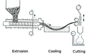
The granulation offers much flexibility. The granules may have different qualities depending on the intented purpose. It nonetheless represents an additional preparation step and requires significant investment costs that are not always justified. A granulation unit consists of three distinct parts (see image 5.2):
- An extruder;
- A cooling system;
- A cutting tool.
The extruder[edit | edit source]
Extrusion is a process that continuously produces profiles. The extruder is a cylinder equipped with an archimedes screw which combines the functions of conveying, compacting, mixing (homogenization) and melting of plastic materials. At the outlet, the plastic paste is extruded (forced passage under pressure) through a path which gives it the desired section(s). For the granulation, the path of the extruder is composed of calibrated circular holes to obtain "spaghetti" of a desired diameter. See here in detail the main components of an extruder:

a. The cylinder
The archimedes screw of the extruder rotates in a solid steel cylinder, sometimes called the "sheath". It is equipped with a resistance allowing to heat it when the internal friction of the flakes can not obtain a high enough temperature for it to melt. It can also be equipped with a
cooling system when the obtained temperature causes chemical degradation of the polymers.
The cylinder is subjected to considerable mechanical and thermal friction. Therefore it is made of a high quality steel to allow good resistance to abrasion and corrosion.
The inner diameter of the cylinder determines the capacity of the extruder, expressed in kilos of extruded plastic per hour. The standard diameters are:
| Diameter (inches) | Diameter (mm) |
| 1½ | 38 |
| 2 | 51 |
| 2½ | 64 |
| 3¼ | 83 |
| 3½ | 89 |
| 4½ | 115 |
| 6 | 153 |
| 8 | 204 |
Table 5.1: Standard extruder diameters
Wherever possible, we prefer to select an extruder with the most largest possible diameter. It will provide greater operation flexibility and it will work with a wide range of resins. The length of the sheath is also an important feature. It is generally expressed by the ratio of length/diameter (L/D). The first extruders were relatively short, with an L/D of about 12. Now, extruders are longer: L/D= 18 to 24 or 30. A larger length improves the homogenization and stabilizes the flow. However, the plastic can be degraded chemically after a too long exposure to high temperatures. For the recycling, we thus prefer a limited length to avoid too significant degradation of polymers.
b. Screw The archimedean screw has several functions for the extrusion:
- It carries the feeding matter up unto the path (transport);
- It plasticizes the material due to a mixing which homogenizes the distribution of heat in the cylinder;
- It increases the pressure progressively which then densifies the material and transfers the necessary force to cross the path.
The screw of an extruder is a cleverly designed part, and is manufactured with great care. It is made of a steel of very high quality (chrome steel, special steel), is precision machined and has undergone thermal and surface treatment. It can neither be manufactured nor repaired by craftsmen. There is no other alternative than to buy it from manufacturers or suppliers. The geometry of the screw is designed to obtain the best conditions for extrusion. There thus exists a great variety in shapes.
The most simple screw has a constant flow but a variable groove depth: the inside diameter of the screw increases from the top (mouth) to the outlet in order to compensate the compaction. The "compression ratio" (input-output volume ratio) is often between 3 and 4. There are also screws with a double helix (variable pitch). Others have a posterior zone containing chicanes or torpilles that break the pudding contained in the screw and thus improve the mixing. Some screws are made of two homogenizing areas separated by a "recreation area" which allow to release any potential gas. Finally, the recent extruders can have double screws of which the flows mesh together parallelly and revolve in the same direction or inversely. This system noticably improves the mixing/homogenization function. The behavior of the plastic in the extruder can be divided into three zones:
- The feed zone: The plastic flakes are introduced into the feeding zone of the extruder through an opening in the hopper. The first zone provides a first compacting of the flakes.
- The transition zone: Gradually and depending on their compaction, the plastic flakes are subjected to intense friction, combined with an injection of heat from the resistances placed in the electric coils around the cylinder, and melt gradually. The internal friction (friction from flakes and increased viscosity of the molten plastic) generates a lot of "mixing heat" in the extruder, so that it is sometimes not necessary to heat the sheath. This is called adiabatic functioning. Sometimes it is even necessary to cool the sheath. Depending on their type and the operating conditions (speed of rotation of the screw, geometry of the screw, sheath temperature, ...), the plastic melts more or less quickly. The part of the screw in which the softening is performed is called the "transition zone". The length of it can be very variable: 2-3 turns in the screw, or otherwise 1/3 to 2/3 of the total length.
- The pumping zone: The last portion of the screw serves to homogenize the molten plastic and to pressurize it to overcome the counterpressure (pressure drop) in the sector. This area, called the "pumping zone", controls and stabilizes the flow in the extruder. An long and narrow pumping zone improves homogenization and stabilization of the flow. It however increases the risk of chemical degradation by internal friction. This is why the plastic waste recycling extruders preferably have a deep pumping zone characterized by a moderate compression ratio (less than 3). The control and regulation of temperature along the extruder and the path is very important. Indeed, viscosity and pressure of the plastic, and therefore the flow varies significantly with the temperature. The temperature control is usually realised using a thermocouple.
The table below shows the common operating temperature range for the different zones in the extruder:
| Type of plastic | T° feeding zone | T° transition zone | T° pumping zone | T° path |
| HDPE | 140 | 160 | 165 | 170 |
| LDPE | 125 | 125 | 130 | 135 |
| PP | 185 | 200 | 220 | 240 |
| Rigid PVC | 155 | 165 | 180 | 180 |
| Soft PVC | 175 | 165 | 155 | 160 |
Table 5.2: Operating temperatures of extruders for different polymers
These temperatures are valid for virgin resins. For recycling, it is preferred to work at a lower temperature and at a slower rotating speed to avoid degradation. This remark is especially valid for PVC which, upon degradation, generates hydrochloric acid (HCl). Besides the risk of inhalation, ..., acid may also corrode the screw and the sheath of the extruder. The rotation speed of the extruder screw is usually between 150 and 300 rpm. On most machines, this speed is adjustable. It is difficult to predict the flow in extruders. This is due to the fact that the flow characteristics of the plastics depend on a complex (not linear) manner on friction and temperature. In general, we can generally consider three main factors that influence the flow of an extruder: temperature, the rotation speed of the screw and the inside diameter of the sheath. Some rules of thumb exist. Thus, regardless of the rotation speed of the screw, the temperature or the type of resin. We can find the following formula in the books:
Failed to parse (Conversion error. Server ("https://wikimedia.org/api/rest_") reported: "Cannot get mml. TeX parse error: Double subscripts: use braces to clarify"): {\displaystyle Q=7_{X}_{d}<sup>2,2</sup>}
with, Q(kg/hour): hourly speed of the extruder; d(inches): inner diameter of the extruder sheath.
Thus, an extruder with a diameter of 3½ inches would have a flow of 110kg/hour. Another simple rule of thumb suggests a relationship between the flow of the extruder and the engine power of his screw:
Failed to parse (Conversion error. Server ("https://wikimedia.org/api/rest_") reported: "Cannot get mml. TeX parse error: Double subscripts: use braces to clarify"): {\displaystyle Q=(2_{t}o_{4})_{X}_{P}} with, Q(kg/hour): hourly speed of the extruder; P(kW): engine power of the screw.
Before considering an investment, we will verify these flow rates from the machine supplier.
c. The filter Despite the washing, the plastic waste can still contain impurities (paper, metals, ...). These impurities can be removed from the molten plastic by allowing them to pass through a filter located in the pumping zone of the extruder. Once clogged, the filter can be changed, cleaned and reused.
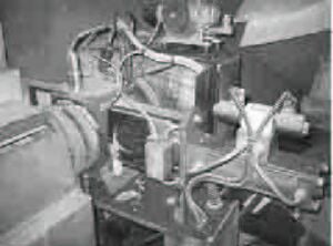
With normal use, the filter is clogged quickly and must be changed at least every minutes. This operation is usually performed manually.
d. The path The path used for the regeneration of the plastic waste is a metal plate perforated by calibrated circular holes through which molten plastic is pushed. This results in molten plastic filaments with a diameter of 2-3mm which will cooled and cut.
The cooling system[edit | edit source]
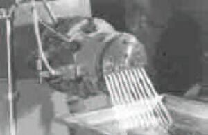
In order to be cooled, the plastic filaments (sometimes called "rods") are directly immersed in a tank of water. In the tank, they are pulled in by the granulator (see next paragraph) and are kept submerged by combs that align them in order to prevent contact between them (see image 5.3). The length of the tank must be sufficiently large so as to effectively cool the plastic. It is proportional to the diameter of the filaments and the speed thereof.
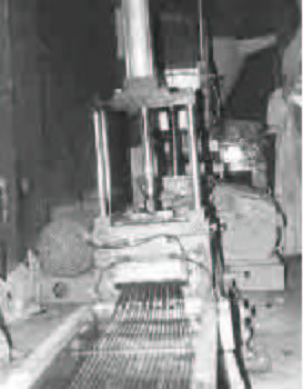
A hot water purging must be continuously carried to replace it by cold water. This water can be recycled eg by using it with the washing of the plastic waste.
The granulator[edit | edit source]
The granulator consists of a wheel with cutting teeth, driven by a small electric motor (1 to 10 kilowatts). It has a dual role. First, it draws in the filaments, allowing them to enter and exit from the cooling bath. On the other hand, the teeth cut the cooled filaments into small granules of 3-4 mm length.
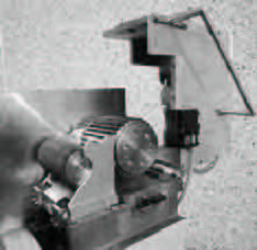
The capacity of the granulator must be sufficiently high so as to keep up with the rate of the extruder. The feeding speed should be adjusted according to the speed of the filaments out of the outlet of the extruder. This speed is generally between 10 and 100 m/min. Once cut, the pellets are collected at the outlet of the granulator and are immediatly placed in bags to avoid contamination.
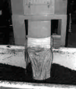
Note: Another possible system is the cutting of hot filaments, directly at the path outlet. The warm pellets fall into a tub of water in order to be cooled.
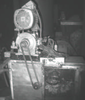
The drain that conveys them to the cooling tank must also be cooled to prevent the granules from sticking to the walls. This can be done using a small sprayer. The water then carries the pellets to the tray.
Workings of a granulation system: The regeneration extruders are machines that are difficult to keep operational. It takes at least an experienced engineer, which has already worked with such machines, for 2-3 systems. In addition, two less qualified persons are required per installation for the feeding of the extruder and for the recovery of the recycled plastic pellets. A roofed and well ventilated room can accommodate this recycling sustem. The extruders are relatively heavy machines that need to be installed on a concrete slab for reasons of stability.
Seeing the installed capacities, it is necessary to have a good electric network at your disposal. The extruders can not handle power cuts as they then cool down and the plastics they contain then clotter up inside. In the case of locating the center in an area that is subjected to frequent power cuts, it is essential to have an electrical generator. This electrical generator will inevitably be large and can represent a very large investment cost. Besides these technical considerations, the energy cost of these machines is not negligible and must be thoroughly evaluated before investing. In India, the main problems encountered by the processing companies are electrical problems (power instability, frequent power cuts, high prices, taxes, others, ...) The extruders can be purged for different reasons: stoppage of machine production, maintenance, change of the recycled polymer, ... The purge can be be limited to only stopping the extruder feeding and letting the machine run until it no longer produces any more material. The screw is then not completely empty. It then still contains about thirty percent of plastics. Upon restart, the materials contaminate the first production matter of the extruder and a period of time will be needed before it can produce good products. Residues obtained when purging (broken filaments, purge blocks, ...) can be cut, shredded and again recycled.
Adding of additives: The granulation step allows the addition of additives such as fillers, plasticizers, stabilizers or anti-oxidants. To get more vibrant homogeneous colors, it is also possible to add pigments or dyes. Pigments are usually oxides or metal salts. They can be bought in the form of powder, but for manipulation reasons, it is always preferable to buy them in the form of pellets. We usually add 1 to 3% depending on the required quality. In India, processing companies add something to these pigments they call "masterbatches". These are capsules which contain several additives such as silicium dioxide for uniformity and handling, dispersing agents (ethers, waxes) and other agents such as silica or titanium salts. These "masterbatches" improve the color uniformity and have no impact on the process.
The extrusion[edit | edit source]
In addition to the granulation described above, the extruders can be used for a multitude of applications, as described below.
Profile extrusion[edit | edit source]
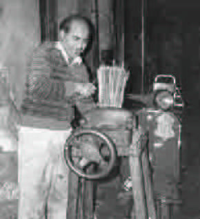
The manufacturing of profiles is achieved using extruders of the same type tho ones described for the granulating. Only the paths placed on at the top of the extruder differ. Thus, depending on the geometry of the path, it will be possible to produce plates, sheets, tubes, rods, pipes, ducts and a multitude of other profiles with complex shapes: window frames, slides, ... The extruder can be fed with recycled plastic pellets or directly with flakes, depending on the desired quality. At the outlet of the path, the profiles must be cooled in cooling baths before being cut to the desired dimensions. The obtained profiles can be used as such (hoses, drainage pipes, plates, ...) or they can be assembled (window frames, sanitation, ...). Image 5.7 illustrates the traditional manufacturing of brushes. These are made using filaments, extruded and cut at forty centimeters. They are then gathered and tied together at the end of a stick of wood serving as the handle.
Blow molding: hollow bodies[edit | edit source]
The blow molding allows to make hollow objects: vials, bottles, drums, toys, industrial parts, ... This is done in two phases:
- We continuously extrude a tube which is cut into the desired length sections (called "paraisons"
- These still warm paraisons are brought into a mold. The mold is closed creating a weld by pressing one end of the paraison extremeties. A blow pipe is inserted into the other end. We then blow air under a few kilos of pressure in, to press the paraison sides unto the inner sides of the mold. After a cooling period, the mold is opened and the thus formed body is ejected. The machine is then ready for a new cycle.
The whole of this shaping is automated, the extrusion being continuous and the blowing discontinuous. This technique is almost impossible to implement artisanally. Specialized equipment and trained personnel is necessary.
Calendering extrusion: sheets, plates[edit | edit source]
The calendering extrusion is a technique used to obtain plastic plates or sheets. It consists of extruding a flat profile and stretching it using successive calenders until a product with the desired thickness is obtained.
The nomenclature of the obtained products depend on their thickness. We will define
- Plates, when the thickness exceeds 1.5 mm;
- Sheets, when the thickness is between 200 microns and 1.5 mm;
- Films where the thickness is less than 200 microns.
The calendering extrusion of films requires precision equipment which makes this technique very expensive. It has been replaced by inflation extrusion.
Inflation extrusion: films[edit | edit source]
The inflation extrusion technique allows to obtain very thin films (up to 10 microns thick) that are used in the manufacturing of bags. It applies to most plastics (HDPE, LDPE, PP, ...). This technique consists of extruding a thin sheeth that is inflated by hot air (see image 5.4). The film, shaped as a bubble, is then flattened by a device composed of converging panels towards spiked wheels. The flattened film, then passes pulling-wheels after being run over by receiver coils.
The air that fills the sheath is inserted through the annular path axis used for this manufacturing. It has a square geometry. An interior and exterior cooling system positioned at the already inflated sheath allows to stop the stretching. This phenomenon is caused by the solidification of the cooled plastic matter, which thus supports the constraints from the inflation.
The obtained rollscan then be cut to the required form to obtain bags, tarps, ... The manufacturing of plastic films is a technique that is not easily achievable using the artisanal method. In addition, it requires high quality resins. The use of pellets made from waste is thus not straightforward. It has nevertheless already been recreated. In Cairo, a waste picker has managed to recreate one such machine after having worked for a few months in a bag-manufacturing enterprise.
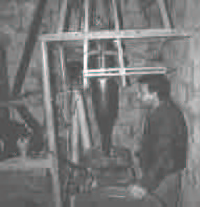
The manufacted plastic balloon is folded and wrapped in rolls of fifty meters. It is then peeled, cut and welded to get small bags. Handles can also be cut. This type of bag is usually sold in toolstores. It avoids the agro-food stores given that the used pellets are from recycled waste.
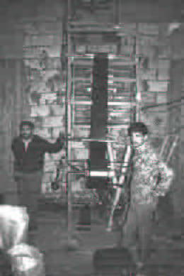
This activity employs 3 people, full time. The space required is a well ventilated room of 30m² The engines and the molten plastic indeed generate much heat and smell.
The injection molding[edit | edit source]
General[edit | edit source]
Injection molding is a transformation process that allows to obtain plastic objects of different shapes. Similar to extrusion, it consists of heating plastic flakes or granules of in order to liquefy them (plastification). The plastic paste is then introduced under pressure into a mold to give it the desired shape. It is therefore a batch process: after the mold has cooled, the part is removed from the mold and the operation can recommence. Injection molding is done using injection presses. These consist of three parts (see image 5.6):
- An injection pot in which the material is plastic. The plastic material is introduced through a feeding hopper and it is gradually heated through contact with the walls of the pot. A piston ensures the transfer of the fluidized material towards the mold through a nozzle.
- A mold in which the plastic in the state of a paste is introduced. It takes the form of the negatively drawn walls to obtain the desired object. Once the mold is cooled (with a possible cooling system), the part can be extracted. The mold is ready for another injection cycle.
- A sealing system necessary to lock the mold during the injection and to permit an opening for the molding.
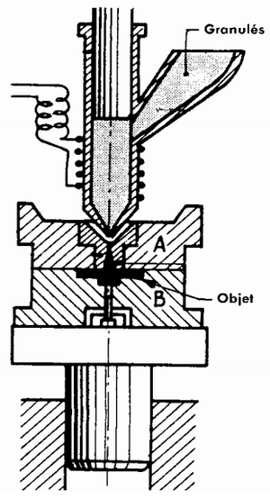
In earlier versions, the plastification (fluidization by heating) is only done using heating ducts surrounding the injection pot. Recent machines have screws that divide the material and homogenize them. A detailed discription of previous models is however useful because these machines have a simple design, reproducible by local mechanical workshops. Experience shows that the artisanal shaping workshops using this type of machine are able to produce parts with added value at low costs.
Injection plunger presses[edit | edit source]
The injection plunger presses have the same design as the press shown in image 5.6. Plastic matter (flakes or granules) are introduced at the top of the injection pot using gravity. This can have an injection capacity that reaches 60 to 70 grams. The piston is moved either manually (via a lever or crank) or via a hydraulic system. A system of heated resistors turned around the injection pot provides the heating. It is covered with an insulating sheath.
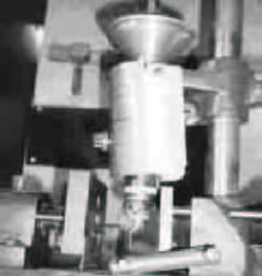
Similar to the extrusion, each type of plastic must be heated to the right temperature as to be able to be injected. Table 5.3 shows the required temperature ranges:
| Type | T° of softening | melting T° | transformation T° | degradation T° |
| HDPE | 125-135 | 130 | 260-310 | 200-240 |
| PVC | 150-200 | 170-190 | 175-200! | |
| LDPE | 102-112 | 110-120 | 160-260 | |
| PP | 160-165 | 168-169 | 250-270 | |
| PS | 70-115 | 180-230 | 250-350 |
Table 5.3: Operating temperatures of extruders for different polymers
The temperature control is one of the most delicate points. It requires good proficiency of the operators. Two methods of temperature control are possible:
- A thermostat can be directly connected to the electric supply of the machine. It shuts off the power supply when the injection pot has the desired temperature. For this, a thermostat covering the temperature range from 0 to 300°C is essential. The disadvantage of this method is that such a thermostat is expensive and fragile.
- Another system is to design a circuit for allowing the varying of the feeding to the heating resistance. The operator can thus control the temperature based on the fluidity of the plastic at the nozzle exit. This method is less expensive but requires some experience from the operator.
The heating resistors are subjected to long working hours and may get damaged. A regular rewinding is thus necessary (at least every 6 months). The end of the injection pot is equipped with a nozzle of which the output channel presses against the mouth of the the input channel which is drilled in the injection mold. To improve homogenization of the material before reaching the nozzle, some machines are equipped with torpilles. These parts divide the flow to better mix and heat them.
Important Note: Never leave the plastic for more than three minutes in the injection pot without injecting it. It may deteriorate, become extremely fluid and drip off due to gravity causing damage (burns, burrs, ...). The molds are delicate and important parts. They can be characterized by their number of impressions, their architecture, their feeding system and their method of temperature control.
- The "imprints" are cavities that represent the object. A single mold can contain multiple imprints. They are then filled with material through the channels.
- The architecture of mold defines the way on which the mold is mounted: two plated molds, three plated molds, ... as well as its closing system and lock.
- The power supply system is the whole of the channels that guide the plastic molten in the imprints. They can be very complex. They must be studied to facilitate the cooling of fluidified plastic in the imprints.
- A mold must always be cold for the object to harden before being removed from the mold. Fluidified plastics matter periodically generate heat, we must thus cool them constantly. This is done through the circulation of a fluid that regulates the temperature.
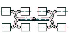
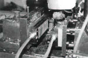
Extremely fine channels allow the venting of gas during the filling without obstructing the plastic. They can be obtained by small molding shots. Some molds can have an ejection system which allows the fast demolding of a piece. The molds are made of adapted steel or sometimes from Zamac. Those in steel are often more expensive, but they are more accurate and their lifetime is significantly longer. The molds in Zamac are mostly chosen when the amount of pieces to produce do not justify a steel mold (orders, limited market, ...).
Injection molding method: The injection is a batch process. Each cycle includes the following steps:
- closure of the mold;
- injection of fluidized plastic into the mold, after having contact with the nozzle;
- cooling of the mold, together with the withdrawal of the plunger and the filling of the injection pot with plastic material (pellets or flakes);
- demolding after withdrawal of the plunger to shift the mold nozzle.
A new cycle can commence.
The amount of injected material corresponds to roughly a third of the maximum injection capacity, defined by the stroke of the plunger. Based on the time required to complete a full cycle and the weight of the objects produced per cycle, it is possible to determine the capacity of a machine with a particular mold. In Cuernavaca (Mexico), a person working on a plunger press is able to do a cycle every 40 seconds. The produced objects are screw plugs. The (three plated) mold has 10 imprints. The hourly production is about 1000 plugs or about 2-3 kg of plastic per day. The room where the presses are installed requires good ventilation, because these machines generate much heat. Each release should be fixed on a solid foundation (preferably metal), anchored to the ground and perfectly horizontal. A foot allows to adjust the press to the required height to ensure contact between the injection nozzle and the mold.
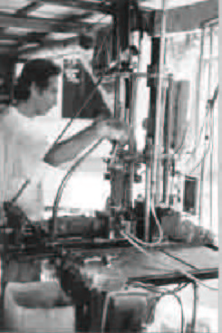
A big advantage of small injection plunger presses is that they can work with monophase power. However, when several machines operate in the same workshop, we must thoroughly verify the operation capacity. Moreover, it is preferable to connect each machine to a specific circuit breaker to avoid significant heat variations brought in by the resistors. The quality of the injected parts may depend on it.
Supplier of injection plunger presses: Vulcano Inyectores S.A. Dr. Ruiz 14 Mexico 7 D.F. Tel. : 578.72.65 578.74.18 Fax. : 674.34.19
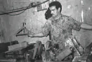
Mexican supplier of plunger presses Price for a used machine (April 2001): ~1000 € Prices for a hydraulic closing system (April 2001): 3.500 € This type of press is no longer found on the European nor North American markets. We find still find them at Indian, Turkish and Egyptian markets.
Injection screw presses[edit | edit source]
Plastics are poor heat conductors, their lamination can be difficult and non-homogeneous (the sides becoming warmer than the inside of the pot). To correct this, most new machines use a movable, tranferable screw. During lamination, the screw is rotated and moved back into the pot. The fluidified matter accumulates at the top of the pot. Once the amount of required plastic is accumulated, the screw is pushed by an actuator that transforms it with the plunger to fill the mold.

In addition to an improved heat transfer in the jar, the screw also homogenizes the material much better. This is an important benefit when working with recycled materials. The same applies when we add various additives such as pigments, fillers, ... Moreover, the objects that can be produced can be much larger: basins, chairs, trays, ... However, the price of such a machine is much higher than that of a plunger press. Investment is rarely justified for the injection of small pieces with a low added value.
References[edit | edit source]
- ↑ An other word granules is "pellets", an other word for "flakes," is "chips" or "dices". A group of pellets is also called "pelletizer". The term "granulator" exists too, but it is sometimes used to characterize the grinder knives. We must therefore first see the device before considering an investment.
- ↑ The injection presses can be horizontal or vertical
