Project goals
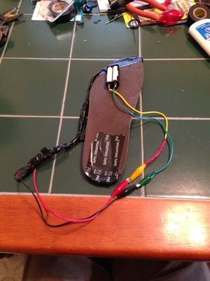
The goal is to construct a piezoelectric energy harvesting device that can generate enough energy to create a noticeable charge in a battery.
Design
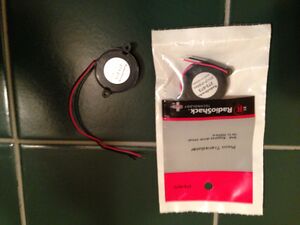
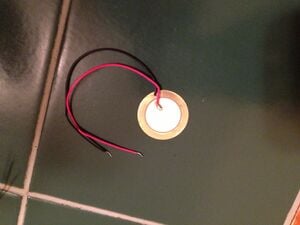
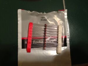
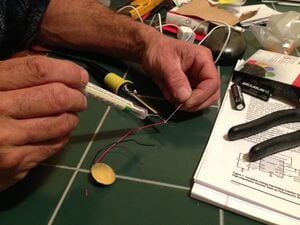
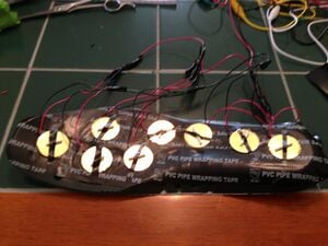
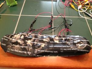
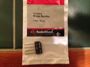
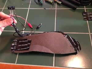
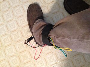
Eight piezoelectric transducer pads were placed under the sole of a shoe and connected to a battery pack. A diode was soldered to each piezo pad, and a rectifier was soldered to the system, before it was connected to the battery.
Results and Discussion
Before testing batteries I drained them with a Mini Maglight bulb. After wearing the shoes with 2 NiCd AAA batteries for half a day the batteries would not light an LED, and they only lit the Mini Maglight bulb for a fraction of a second. After wearing the shoes with 2 NiMH AA batteries for a full day the batteries did light an LED, and they lit a mini Maglight bulb for almost half a minute.
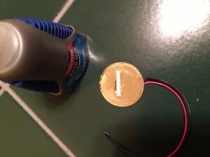
When connected to an LED a piezo pad would turn on the LED for a fraction of a second when tapped. The method which produced the brightest response was when the led was bent slightly and release as a flicking motion. The q-tips were placed under each piezo pad to increase the amount of bend each pad receives when stepped on, but applying pressure by stepping is an inefficient way to release charge from the piezo pads. When testing one piezo pad connected to a battery a noticeable charge was created in the battery, but it was not significant enough to rule out the possibility that the battery was only excited by the piezo pad. Piezoelectric pads have very small current outputs compared to their voltage outputs, which makes it challenging to effectively charge a battery with them.
After using the soles for a couple of days some of the piezo pads don't seem to work as well as they used to when connected to an LED light to test. The q-tip may bend them too much, particularly under the heel.
Video Demonstrations
LED connected to sole
NiMH Batteries connected to LED
NiMH Batteries connected to Mini Maglight
Next steps
- More testing
- Alter the system to increase efficiency.
- Create a better battery charger that can effectively transfer the small and irregular amount of current produced by piezo pads.
Conclusions
More testing must be done to confirm whether or not the piezo sole actually charged the batteries, but the system did demonstrate the piezo pad's ability to turn on an LED light and produce some electricity. An alternately constructed system could charge a battery, but the efficiency of piezoelectric pads is very low for harvesting the mechanical energy provided by walking.
