


This project is part of a collection on open source optics meant to radically reduce the cost of experimental optical equipment. See: Zhang C, Anzalone NC, Faria RP, Pearce JM (2013) Open-Source 3D-Printable Optics Equipment. PLoS ONE 8(3): e59840. doi:10.1371/journal.pone.0059840 open access
This Arduino-controlled open-source automated filter-wheel changer is set up to move to 8 different filter positions. Normally these devices are used in scientific experiments that need precision optics. Commercial versions cost over $2,500 and you can make this yourself for less than $50. So if you make just one -- you more than justify the purchase of your own open source 3-D printer!
Bill of Materials[edit | edit source]
Non Printed Parts[edit | edit source]
28 M3x10 Screws
8 M3x22 Screws
1 M3x10 Set Screw (Grub Screw)
33 M3 Nuts
1 Nema 17 Motor [1]
1 Arduino Uno
1 Motor Shield from Adafruit
1 OptoEndstop
Printed Parts[edit | edit source]
All printed parts designs can be downloaded here: http://www.thingiverse.com/thing:26553
7 Filterwheel Segments (pie slice segments)
1 Filter Wheel Final Segment (This one is different from the rest)
1 Motor Hub
1 Motor Mount
8 Filter Brackets
1 Optical Switch Flag
Instructions[edit | edit source]
With your favorite RepRap variant print preferably in black ABS or PLA in order to cut down on reflected light.
Part 1-Filter Wheel[edit | edit source]
- Start off by Printing the Motor hub in ABS or PLA. We used a 35% infill with 2 perimeters and 2 solid layers.
- Then print off 7 Filter wheel Segments. We suggest printing these out in PLA to prevent warping. Warped prints are not useable. After each print, drill out all the holes. An 1/8" drill bit works fine if you don't have a 3mm bit.
- Attach the Segments to the Motor Hub by first placing a M3x22 screw through the Motor hub bottom piece, the segment, then the top piece, attach a nut to the screw. Do not tighten all the way, this can make aligning the segments more difficult. Once a segment is placed next to it, rotate them so that the tab in one aligns with the slot in the other place and place an M3x10 screw through the hole, and tighten with nut. To get them to fit, some shaving down of the edges might be necessary with a file or sandpaper.
- When it comes to the final Segment, print it out. (It does have a longer bridge then the rest, so you might want to use a fan to cool it. We also slowed the print speed of bridges in Slic3r from 60 mm/s to 30mm/s. It did a much nicer bridge.) When it is finished drill out the holes, just as before. Then take the piece, next to the final one, with the slot in it, and cut out the small portion of the print at the edge of the bridge. Slide the final segment in, it should fit perfectly, if not, shave down the edges until it does.
Part 2-Filter Wheel Case Bottom[edit | edit source]
- Print out the motor mount. Drill/clean out the holes and place an M3 nut in all of the nut traps on the bottom. Screw a Nema 17 Motor on to the bottom and tighten.
- Then print out the filter Wheel Case Bottom Segments. We again used PLA. These are relatively thin so when you pull them off be careful (e.g. wait a couple minutes after the print before grabbing them. Again - if they flex, they are useless).
- Start by placing a screw through the case segment then into the motor mount. The screw should catch the nut on the bottom. Do not tighten all the way, as this will make aligning future segments more difficult.
- Place the next Segment on and do the same, then rotate together with one's tab inserting into the other's slot. Place an M3x10 Screw through the hole and then tighten. Be sure to place Segments 2 and 3 next to each other.
- When all of the Segments are in place, tighten all the screws.
Part 3- Filter Wheel Case Top[edit | edit source]
- Print out the Filter Wheel Case Top Hub and drill out all the holes.
- Then Print out the filter Wheel Case Top Segments. I did these in PLA as well, because warp will render them useless. These are relatively thin so when you pull them off, be careful, I would suggest waiting a couple minutes before grabbing them, if they flex, they're useless.
- Start by placing screws in a segment, then through the hub, and then place a nut on the other side and tighten. As with all the other cases, do not tighten all the way as this will make aligning the Segments more difficult.
- Place the next Segment on and do the same, then rotate together with one's tab inserting into the other's slot. Place an M3x10 Screw through the hole and then tighten. Be sure to place Segments 2 and 3 next to each other.
- When all of the Segments are in place, tighten all the screws.
Part 4- Final Assembly[edit | edit source]
- Take the Filter wheel case bottom and the Filter Wheel. Place the bottom of the filter wheel over the Nema 17 Motor shaft, place the grub screw in and tighten.
- Then take the motor hub top and place over the bottom, the hole in the top must align with the hole in the bottom. Place nuts in all the Nut Traps surrounding the outer edge. Then place Screws through the holes in the top and tighten the screws.
Customization[edit | edit source]
The OpenSCAD file is included here for those that want to alter the filter wheel for their own experiments. With it you can change the size of the filter, shape, number of filter holder pie slices, etc.
Electronics[edit | edit source]
Circuit[edit | edit source]
Design[edit | edit source]
Figures 1-4 below show the layout of the electronics the pins of both the optical sensor and the motor sheild and a basic wiring diagram.
-
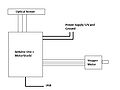
Fig. 1 MotorShield is attached to the Arduino Uno
-
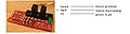
Fig. 2 Optical Sensor Pins connections
-
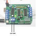
Fig. 3 MotorShield Pins connections
-
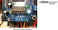
Fig. 4 Wiring diagram


- Make sure 12V and GND from power supply are properly connected to the MotorShield (written on the board).
- Remove the Power Jumper of the MotorShield!
- If using a stepper motor from Adafruit, the connections are, from M1 to M2: Brown, Green, Yellow, and Red; Gnd pin is not necessary (see Fig. 4). For other motors you have to findthe correspondent wiring for each coil of the motor.
Software[edit | edit source]
- AFMotor.h library necessary: http://www.ladyada.net/make/mshield/use.html
Required Software:
- Arduino 1.0 or later -- http://arduino.cc/en/Main/Software
- Processing 1.5.1 or later -- http://processing.org/download/
MOST code:
Includes:
* Filter_Wheel_V1_by_Rodrigo.ino
* Filter_Wheel_Computer_Interface_by_Rodrigo.pde
Instructions
- Upload the Firmware: Filter_Wheel_V1_by_Rodrigo.ino to Arduino Uno using the Arduino software.
- Connect the Filter Wheel to the USB port.
- Run Filter_Wheel_Computer_Interface_by_Rodrigo.pde using Processing, or use any application provided* for Windows, Mac or Linux. (e.g.application.windows64 folder).
- Java JRE necessary.