The Use of Organic Residues in Rural Communities (UNU, 1983, 177 p.)
Special working group on biogas
Report of the session on biogas
In introducing the session on biogas, the Chairman, C.G. Hedén, emphasized the positive aspects of biogas technology: employment and establishment as an alternative source of energy. On the other hand, the need for more research and development on the microbiological, technological, and ecological costbenefit analyses cannot be denied. Special attention was given to the aspect of gross energy requirement, which hitherto has been glossed over in the enthusiastic implementation and promotion of biogas technology. In highlighting the areas for discussion, Hedén dealt with the energy requirements of the process, the engineering aspects (e.g., stirring), and the different types of construction and insulating materials. Integration of biogas technology into rural development schemes was another area specifically mentioned on account of the immediate, multiple associated benefits that result from such integration.
A.A. Lyamchai described the rationale behind the promotion of biogas technology, particularly in the rural areas of Tanzania. Tanzania, with an agrarian tradition, is ideally suited to use agricultural residues for the production of feed, fertilizer, and fuel as a result of biogas technology implementation.
The national programme started in 1975 following collaboration with the Khadi Village Industries Commission in Bombay, India. The experience resulting from such collaboration was described. Since then several local innovations have been tried successfully.
SIDO has technicians who provide on-the-spot training and help to get rid of bottlenecks Constraints were also emphasized, e.g., climatic considerations, lack of accessories locally, etc. A 3 m³ plant costs US$750, which is outside the reach of many rural people. Other major contraints are the cost of the installation, operation, and maintenance of biogas plants. Lack of technical experts and servicing personnel constitute a serious drawback. Various problems of digester construction and use of materials were described: an Indian design used steel for the digester, which, of course, is very expensive; a Chinese design using earth materials has been tried, which is cheap but allows leakage of effluent; and a Tanzanian design built with oil drums has proved not to be durable.
E.J. Da Silva gave a brief resume of biogas technology that has been promoted by a number of agencies. He stressed the need for integrated biogas farming systems and cited examples in the Philippines and Brazil. In addition, he also emphasized a point that has often been glossed over, viz., social acceptability and psychological prejudice to the deployment of certain resource materials. He also pointed out that the trend is now towards the use of bag digesters.
C.V. Seshadri dealt with the experiences in the laboratory versus those at on-site locations. He provided more details on the "red earth" bag that is used by Chinese scientists. The advantage of this bag is that it is UV-resistant. Seshadri stressed the importance of integration, e.g., biogas to run diesel engines and small pumps. He emphasized the fuel-food combination of the overall system. For example, fertilizer is an important constituent of the multi-component system. He reiterated the necessity of initiating appropriate measures to ensure social acceptability.
T.K. Chose provided more information on the technological aspects of biogas production. He also cited the example of a school in India that has run for a number of years on biogas produced from dung. In stressing productivity as a major problem, he highlighted some of the major bottle-necks, e.g., temperature fluctuations, choice of suitable substrates, concomitant gases occurring with CH4 generation, and efficiency of digestion of raw materials, etc.
C.G. Hedén pointed out the need for thermophilic digestion as a means of destroying pathogens.
In the discussion that followed, a number of speakers made suggestions, and both sought and provided clarifications. These were taken into consideration in the following statement.
Statement of the Working Group on Biogas
Considering the significance of rural biogas production as a means of ensuring efficient combustion in heating processes that can improve food digestibility and water safety, and also the potential of digestion to convert potentially hazardous materials into a useful nitrogen and trace-element fertilizer, the biogas group:
- Regards biogas production as an important element in strategies to lift the levels of health and selfreliance in agricultural communities, particularly wherever large amounts of dung are generated;
- Regards digestion as a key function within integrated bioconversion systems where it can be combined with a variety of other technologies that, in some instances, can achieve substantial synergistic effects on the level of nutrition;
- Believes that biogas technology, applied at the village level, has not been used as it could be; it is suitable for an international effort aimed at systematic research and information exchange.
In particular, the group recommends:
- That emphasis be given to the choice of suitable construction materials commensurate with the existing economic infrastructure (bricks, clay, etc.) in the development of simple, small-scale, rural units;
- That systems for efficient temperature control based on solar energy and heat accumulation be developed;
- That cheap and simple devices for stirring based on locally available resources be considered;
- That the possibility to optimize acidification and gas production steps be studied in simple equipment, and methods to achieve stability be developed;
- That the fate of pathogens is evaluated in the type of simple, small-scale units that might be appropriate for village use;
- That the gas yield and productivity of various substrates and residues be studied.
Notes on biogas systems and biotechnology transfer techniques
The following references will help in understanding the state of the art of biogas technology in India, China, and, to some extent, South-East Asia. The first reference is highly recommended for its detailed engineering analysis.
- "Studies in Biogas Technology." In Indian Academy of Sciences Proceedings "C," vol. 2, part 3, pp. 357-393. Indian Academy of Sciences, Bangalore 560 006, India, 1979.
- "Biogas Technology in the Third World." International Development Research Centre, Box 8500, Ottawa, Canada K1G 3H9, 1978.
- "Compost Fertilizer and Biogas 'Production' from Human and Farm Wastes in the PRC." International Development Research Centre, Box 8500, Ottawa, Canada K1G 3H9, 1978.
- MCRC Technical Notes, no 1. Murugappa Chettiar Research Centre, Madras, India, 1977.
A biogas plant can be divided into three parts: digester, inlet and outlet slurry pits, and gas holder. Construction requirements include digging and earth removal, masonry work, mechanical work, and supervision (until self-reliance is achieved). A central consideration in plant design should be to aim to rely as far as possible on local materials and to use as little welding and as few advanced machine operations as possible.
Two design concepts will be considered here. The first, an Indian design described by the Murugappa Chettiar Research Centre (MCRC), uses a conventional digester and a balloon gas holder; the balloon material has to be bought. The second is a modified Chinese design using bricks, steel rods, lime mortar, cement, and steel pipe for the gas outlet. All the biogas plants are working satisfactorily. The first one described under concept 1 has worked for over two years with only one cleaning.
Concept 1
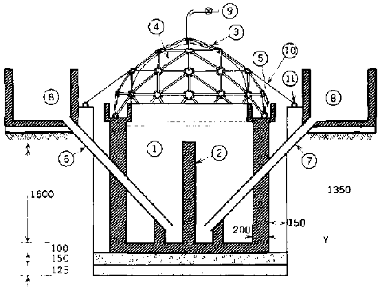
The Annex below gives details on how to calculate the parameters for sizing a biogas plant. Figure 1 shows a conventional KVIC (Khadi Village Industries Commission) digester for four cows. The inlet and outlet pipes are of cement and lead in from slurry pits made of brick and cement.
The plant is a hybrid between the floating gas holder and the Chinese rigid-roof designs. The vinyl balloon is partially flexible and results in slight movement of the gas holder. However, it also relies on the hydraulic head of the slurry pits to equalize forces inside and outside the digester. The water seal helps to prevent leakage from below the balloon and maintains a positive pressure of about 25 cm of water gauge.
FIG. 1. Biogas Plant. (1) Digestion chamber, (2) dividing wall, (3) geodesic dome, (4) heat-sealed PVC gas holder, (5) water sealing, (6) inlet pipe for slurry, (7) outlet pipe for slurry, (8) mixing pit (80 x 80 x 40 cm), (9) gas outlet, (10) nylon cord, (11) hooks. All dimensions in millimetres.
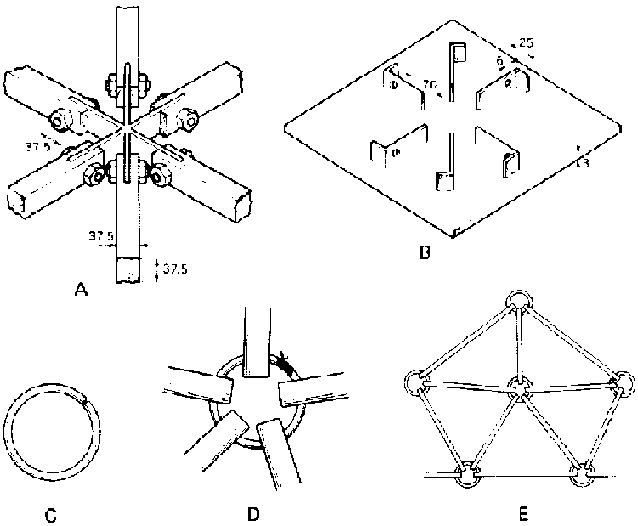
The balloon is fixed to a geodesic dome of wood and steel whose perimeter is immersed in the water seal. The balloon, made of heat-welded PVC panels, is tied inside the geodetic frame and is folded outside under the bottom of the frame. The original design for this structure involved hub joints requiring welding and precision carpentry (fig. 2A and B), both usually unavailable in villages. In an improved, simplified design, the hubs are just 6-mm steel rods bent into a ring shape, and PVC pipe or bamboo rods (exactly drilled) form the struts (fig. 2C-E). A geodesic structure of this simplified design was built in half a day in the village. The balloon was just a whole sheet of PVC or polyethylene film that was neither heat-sealed nor welded. The cost of this dome and balloon was about one-tenth that of the first unit.
Concept 2
FIG. 2. Two Types of Hub Assembly. A: Six-strut welded hub. B: Template for welded hubs. C: 6 mm steel rod bent into a ring, approximately 100 mm in diameter, for simplified hub. D: 25 mm PVC pipe (or bamboo) struts threaded onto the ring, and the ring tied with wire. E: Five-element hub and strut assembly.
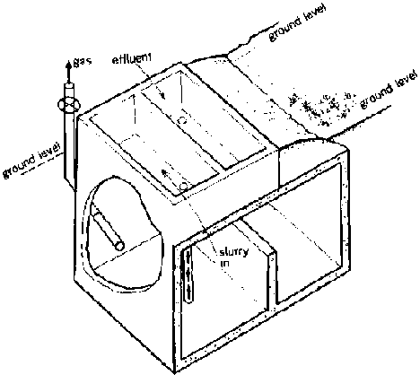
A modified Chinese biogas plant (fig. 3) was made to handle the output of three cows. The modification was that the slurry and effluent pits were mounted on top of the plant to (a) eliminate leakage and (b) simplify the slab design. Three roof slabs were cast with 8-mm steel reinforcement, and two of them were covered with slurry pits. The third (openable for inspection) was loaded with clay and sand to hold it down and prevent leakage. The digester was made in square cross-section (see ref. 1), and the ratio of height to depth was 1:1. It was constructed of brick and lime mortar. The exit gas pipe was sealed in an inclined position to recover condensation. There was a low partition to separate inlet and outlet.
Annex: Calculations for KVIC Biogas Plant
Water hyacinths, other aquatic weeds, and algae can be digested anaerobically to produce biogas. We have constructed one biogas plant and are experimenting with other designs. The plant has two parts: a digester section and a gas holder.
FIG. 3. Chinese Biogas Plant Design
The digester is of standard KIVC design, consisting of a cylindrical underground chamber using 23-cm (9 in.) brick walls and a concrete floor. It has two standard 10-cm (4 in.) cement household pipes for the inlet and outlet. A feed trough, slurry pit, and soaking pit for the digested slurry are provided. Figure 1 shows the details. The only departure from the standard design is provision of a water trough to hold the gas holder (as explained below).
The gas holder consists of a geodesic dome made of wood, to which a vinyl balloon is secured. The balloon is made of heat-sealed vinyl fabric available on the market. The whole assembly sits inside a water trough that serves two purposes: it prevents gas leakage through the water seal if filled with 20 to 30 cm of water, and it helps to anchor the balloon. Hooks around the gas dome also help to secure the structure so that it does not blow off under pressure. The dome struts and hubs were made as shown in figure 2A and B.
| Design of Biogas Plant | |
| Number of cows | 4 |
| Assuming 1 cow produces | 10 kg of dung/day |
| Amount of dung produced by 4 cows | 40 kg |
| Amount of gas produced by 1 kg of dung | 0.05 m³ |
| Amount of gas produced by 40 kg of dung | 2 m³ |
| Daily requirement of gas for cooking and lighting | |
| for 1 person | 0.5 to 0.6 m³ |
| 2 m³ of gas per day will provide cooking and lighting for |
2/ 0.6 to 2/0.5 = 3 or 4 persons |
The volume of the fermentation well should be at least 30 times as large as the daily input. Since manure is usually retained in the fermentation well for about six weeks, it is desirable for the well to be about 45 times the volume of the daily input.
| Using a 1:1 ratio of cow dung and water: | |
| Daily input of cow dung | 40 kg |
| Daily input of water | 40 kg |
| Total input | 80 kg |
| Volume of the well required | |
| (45 times the daily input) | 80 x 45 = 3,600 kg |
| 100 kg of dung and water occupy | 1 m³ |
| 3,600 kg of dung and water occupy | 3.6 m³ |
| Digester tank capacity required | 3.6 m³ |
The gas holder volume should be enough for 60 to 70 per cent of one day's production.
| 70 % of 2 m³ gas | [70 x 2] /100 = 1.4 m³ |
| Digester tank capacity | 3.6 m³ |
| Gas holder capacity required | 1.4 m³ |
Size of the Digestion Tank
Assume 1.75 m as the internal diameter of the digestion tank.
| The depth required will be | 1.5 m |
| Using a 20 cm thick wall, the external diameter will be | 1.75+0.2+0.2m = 2.15 m |
Size of the Gas Holder
A hemispherical PVC balloon is used as the gas collecter.
| Assuming diameter of the dome to be | 1.9 m |
| Volume of the dome (half sphere) | 1.795 m³ |
| Design of Dome to Support the Gas Holder | |
| Type |
2 frequency dome, Class I, |
| Method I | |
| Diameter of dome | 1.95 m |
| Radius of dome | 0.975 m = 38.38 in. |
| Length of struts (including hubs) | |
| Long struts |
radius of dome x 0.618 = 23.75 in. |
| Short struts |
radius of dome x 0.5465 = 21 in. |
| Distance from centre of hub to centre of hole at end of strut | 2.75 in. |
| Length from centres of holes at each end of strut to ends of strut | 1.5 in. |
| Actual length of long struts | 23.75 in. - (2 x 2.75 in.) |
| + (2 x 1.5 in.) = 21.25 in. | |
| Hole-to-hole distance | 18.25 in. |
| Actual length of short struts |
21 in. - (2 x 2.75 in.) + (2 x 1.5 in.) = 18.5 in. |
| Hole-to-hole distance | 15.5 in. |
| Number of long struts required | 35 |
| Number of short struts required | 30 |
| Number of five-element hubs required | 6 |
| Number of six-element hubs required | 20 |


