Joe Raftery (talk | contribs) No edit summary |
Joe Raftery (talk | contribs) (template:VITA added) |
||
| (7 intermediate revisions by 3 users not shown) | |||
| Line 1: | Line 1: | ||
{{ | {{Template:VITA}} | ||
'''FORWARD:''' This page is being ported from the [[MICROFICHE REFERENCE LIBRARY]]. This is not an exact port of the original document and is currently a work in progress. The following content was designed by the [[Volunteers in Technical Assistance]] and was used as a project of Volunteers in Asia. This file is now out of print. The excerpts of this text will help in the construction of a rural electrical system. | '''FORWARD:''' This page is being ported from the [[MICROFICHE REFERENCE LIBRARY]]. This is not an exact port of the original document and is currently a work in progress. The following content was designed by the [[Volunteers in Technical Assistance]] and was used as a project of Volunteers in Asia. This file is now out of print. The excerpts of this text will help in the construction of a rural electrical system. | ||
| Line 65: | Line 65: | ||
===== THREE PHASE AC ===== | ===== THREE PHASE AC ===== | ||
A lawnmower engine has one cylinder. An automobile engine has six or eight. The automobile engine receives six or eight pushes per revolution compared to the single push of the lawnmower engine. It would be convenient if an electric motor could receive more pushes per revolution. This happens with three phase AC. A generator is so constructed that it generates three alternating voltages, but they reach their maximum values at different times. A three phase motor has three coils which each connect to a different "phase" of the three phase generator. Thus the motor is getting six pushes (two pushes from each phase) in the same period of time that a single phase motor gets only two pushes. | A lawnmower engine has one cylinder. An automobile engine has six or eight. The automobile engine receives six or eight pushes per revolution compared to the single push of the lawnmower engine. It would be convenient if an electric [[motor]] could receive more pushes per revolution. This happens with three phase AC. A generator is so constructed that it generates three alternating voltages, but they reach their maximum values at different times. A three phase motor has three coils which each connect to a different "phase" of the three phase generator. Thus the motor is getting six pushes (two pushes from each phase) in the same period of time that a single phase motor gets only two pushes. | ||
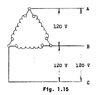
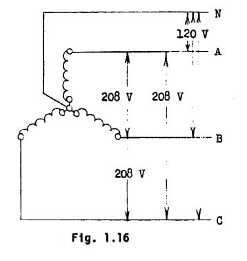
The advantage of generating three phase power is single phase power can also be obtained by connecting the circuit to a single phase, rather than all three. Also, three phase motors are more efficient, simpler, less expensive to buy and run. There are two ways to connect loads to a three phase generator. In Fig. 1.15 and Fig. 1.16 the generators are the same, the diagrams show the three coils which have voltage induced in them by a rotating electromagnet. In the diagrams the arrangement of the coils is different but only for convenience in drawing. The coils each generate 120 V. The voltages obtained with each type of connection are indicated. | The advantage of generating three phase power is single phase power can also be obtained by connecting the circuit to a single phase, rather than all three. Also, three phase motors are more efficient, simpler, less expensive to buy and run. There are two ways to connect loads to a three phase [[generator]]. In Fig. 1.15 and Fig. 1.16 the generators are the same, the diagrams show the three coils which have voltage induced in them by a rotating electromagnet. In the diagrams the arrangement of the coils is different but only for convenience in drawing. The coils each generate 120 V. The voltages obtained with each type of connection are indicated. | ||
Delta Connection- The delta connection of a three phase generator, which resembles the Greek letter A (Delta), is shown in Fig. 1.15. | Delta Connection- The delta connection of a three phase generator, which resembles the Greek letter A (Delta), is shown in Fig. 1.15. | ||
| Line 467: | Line 467: | ||
Motors are not rated in watts as are other electrical loads, they are rated in horsepower. This is because motors consume electrical power in proportion to the amount of power they are | Motors are not rated in watts as are other electrical loads, they are rated in horsepower. This is because motors consume electrical power in proportion to the amount of power they are | ||
[[Category:Electricity]] | [[Category:Electricity]] [[Category:VITA]] | ||
[[Category: PH254]] | |||
[[Category:Energy]] | |||
[[Category: Construction]] | |||
[[category: Peace Corps]] | |||
Revision as of 21:42, 3 May 2011
FORWARD: This page is being ported from the MICROFICHE REFERENCE LIBRARY. This is not an exact port of the original document and is currently a work in progress. The following content was designed by the Volunteers in Technical Assistance and was used as a project of Volunteers in Asia. This file is now out of print. The excerpts of this text will help in the construction of a rural electrical system.
OVERVIEW
The purpose of Electrification is to provide power to do work. This work my be running a Pump, lighting a house, or numerous other jobs. Controlled Power is very important in all our lives. Uncontrolled power can be very dangerous. The Electrical worker must understand the basic principles of Electricity, and how to control electrical power. If he does not have this knowledge he will be handling uncontrolled power, at the risk of life, property, or wasted power.
BACKGROUND ESSENTIALS
These are all key words or terms that anyone proceeding through this work should be familliar with:
Electrical circuit, Ohm's Law, Heat, Magnetism, Light, Parallel circuit, Series circuits, Matter, Electron, Orbits, Nucleus, Atoms, Electric charge, Proton, Current, Generator, Amperes, Ammeter, Direct current, Pulsating (DC) current, Alternating Current, Voltage, Resistance, Power, Energy, Heat, Light, Electromagnetism, Induced Voltage, Meter, Voltmeters, Wattmeters, Multimeter, Voltage Drop.
The total Resistance of a Parallel circuit decreases with an increase in the number of devices operated. This is apparent since an increase in the number of paths for current results in a decrease in total resistance. Remember: The total Resistance of a parallel circuit is always smaller than the smallest resistor of that circuit. The total Resistance can be found by applying the correct voltage to the circuit and measuring the total current taken. The total Resistance is then determined by applying Ohm's Law.
Resistance of circuit = (Voltage/Current)
The total circuit resistance can be found by an application of the following formula which applies to any parallel circuit. This formula is known as the Reciprocal Formula.
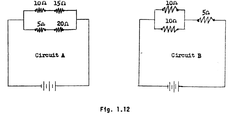
The total resistance of Circuit A can be figured by parts. The two 10 ohm loads in parallel, considered alone have a resistance of 5 ohms. Thus circuit A is equivalent to two 5 ohm resistances in-series, or a total resistance of 5 + 5 = 10 ohms.
The total resistance of Circuit B can also be figured in parts. It is two series circuits which are in parallel to each other. It is the equivalent of tm, 25 ohm resistances in parallel. Thus the total resistance is: 25 = 12.5 ohms.
The most common series parallel circuit is the control of several loads by one switch. The switch is in series with parallel loads.
ALTERNATING CURRENT PRINCIPLES
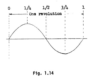
An alternating current can be generated by rotating a coil magnetic field. The voltages induced as the coil makes one revolution are shown in Fig. 1.14. The part of the graph below axis indicates voltage in the opposite direction.
POWER FACTOR
In AC circuits, especially circuits that have large motor loads, the Apparent power is not always the same as the Effective power, as measured with a wattmeter. The effective power is often less than the Apparent power. To measure the amount that these differ we define the term power factor:
To measure the power factor of a circuit, measure the effective power with an AC wattmeter, measure the current with an AC ammeter, and measure the voltage with an AC' Voltmeter.
It is desirable to have as high a power factor as possible. A low power factor means larger conductors are needed to supply the same Power. Power factor can be corrected by installing capacitors into the system. They use no power but correct the power factor. Let the engineer in charge of the project decide when Capacitors are needed and let him decide upon the size needed. Capacitors store power. They are dangerous even when disconnected. Handle with extreme care and always with the terminals connected together.
AC MOTORS
There are many ways to build AC motors. However, they all operate on the same principle. In all AC motors an AC Voltage is applied to stationary coils, which produce a varying magnetic field that changes at a speed proportional to the frequency of the current. The rotating coil rotates in an effort to line up with this changing field.
SINGLE PHASE AC
All the material about alternating current so far has been concerned with, single phase AC. The voltage reaches a maximum twice during each cycle (once in each direction). Therefore an AC motor receives two "pushes" each cycle.
THREE PHASE AC
A lawnmower engine has one cylinder. An automobile engine has six or eight. The automobile engine receives six or eight pushes per revolution compared to the single push of the lawnmower engine. It would be convenient if an electric motor could receive more pushes per revolution. This happens with three phase AC. A generator is so constructed that it generates three alternating voltages, but they reach their maximum values at different times. A three phase motor has three coils which each connect to a different "phase" of the three phase generator. Thus the motor is getting six pushes (two pushes from each phase) in the same period of time that a single phase motor gets only two pushes.
The advantage of generating three phase power is single phase power can also be obtained by connecting the circuit to a single phase, rather than all three. Also, three phase motors are more efficient, simpler, less expensive to buy and run. There are two ways to connect loads to a three phase generator. In Fig. 1.15 and Fig. 1.16 the generators are the same, the diagrams show the three coils which have voltage induced in them by a rotating electromagnet. In the diagrams the arrangement of the coils is different but only for convenience in drawing. The coils each generate 120 V. The voltages obtained with each type of connection are indicated.
Delta Connection- The delta connection of a three phase generator, which resembles the Greek letter A (Delta), is shown in Fig. 1.15.
Fig. 1.16 shows the same generator connected similar to the letter Y. This connection is sometimes referred to as a star connection.
Fig. 1.15 Fig. 1.16
TRANSFORMERS
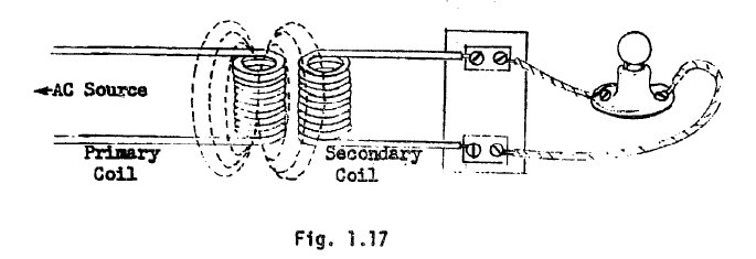
A moving magnetic field generates an electric current in a conductor, and an alternating current flowing in a conductor produces an alternating magnetic field. These two effects can be combined in a circuit such a3 Fig. 1.17.
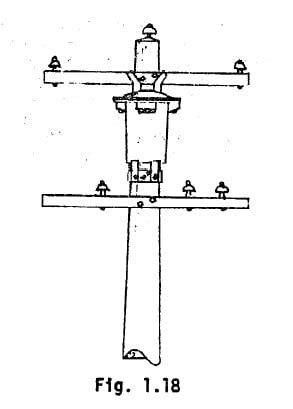
One coil has a current flowing in it. It is an AC current that sets up an alternating magnetic field around the coil. If another coil is placed next to it, there will be an alternating current induced in it by the magnetic field. The first coil is the primary, the second coil is the secondary, and the combination is called a transformer. Most commercial transformers appear as, shown in Fig. 1.18.
Transformers can change voltage. If there are twice as many loops in the coil of the secondary as there are loops in the primary, the voltage in the secondary will be twice the voltage of the primary. This ratio is called the turns ratio, or voltage ratio. A transformer which will change the voltage from 1,000 V. to 100 V. is called a step down transformer. A transformer that would raise the voltage would k called a step up transformer.
THE ELECTRICAL SYSTEM
An electrical system is made up of seven major parts. These are: 1. The generator plant 2. Transmission lines 3. Substations 4. Distribution lines 5. Distribution transformers 6. Secondary lines 7. The house system Each of these parts has components designed to protect or control the system. Throughout the system are switches to disconnect at of the system from the power, so that part of the system can be safely worked on. Each part of the system to protect that part from has fuses over-current. The transmission and distribution lines have lightning protectors to make lightning strikes harmless to the system.
The system is connected as follows. The generating plant is the source of power. If it must be transmitted a long-distance the voltage is stepped up at the generating plant by a transformer. This reduces the current flow through the transmission lines which decreases the voltage drop. At a substation this Voltage is reduced by another transformer and is then distributed over the distribution lines to the area where the power is to be consumed. Near the houses a distribution transformer steps the voltage down to the supplied voltage and which is supplied to the house systems.
SAFETY
Safety must be stressed at all times in all electrification work, whether or not work is being done with electrical currents present. Instructors must stress safety every time they teach a skill. They must stress safety every time they describe a procedure. Every skill and procedure has a safe way of being done and many ways that are unsafe.
This section of instruction describes how electric shock is received, why it is dangerous, and how to treat someone who has received a shock. The major protection from shock is a properly grounded system, so the theory of grounding should be taught. Exactly what to ground and how to ground it should be stressed in later sections at the time that the installation techniques are being taught.
ELECTRIC SHOCK
An electric circuit is a path through which electric current flows. When a person's body becomes part of a circuit, current will flow through his body. This current my: 1. Knock the person unconscious. 2. Give the person a bad burn. 3. Stop the person's breathing. 4. Stop the person's heart.
SAFETY PRECAUTIONS
Electricity cannot be seen, smelled, or heard, so it is impossible to tell weather a wire has one volt running through it, 1000 volts. You should treat every electric wire as if it were dangerous. Before approaching any electric wire, first study the whole electric system to see how this particular wire is connected, and if possible, measure the voltage and current in the wire with a voltmeter and an ammeter. The following DO'S and DON'TS, if carefully observed, should prevent accidents:
1. Always disconnect the electric wire from the source of current and voltage before working on it 2. Always use a test light, a voltmeter, or an ammeter to determine whether the line has a voltage In it and how much the voltage is. 3. Always wear dry gloves when approaching any electric wire. 4. Always pull the disconnected end of an electric wire well away from the source of current to create an air gap. 5. Never touch an electric wire when your feet are in water or on the ground. 6. Never let one of the three wires in a three-phase circuit touch round or one of the other wires. This sort of contact will create an electric arc and intense heat. 7. Never work on a line which has more than 250 volts running through it line-to-ground or form phase-to-phase. 8. Never replace a fuse without disconnecting all appliances and motors connected to the line. 9. Never use metal tools or wear metal jewelry (rings, I.D. bracelets.) around electric wires. Always use tools with wooden, plastic, or insulated hand grips.
RESCUE AND FIRST AID TECHNIQUES
When someone touches a "live" wire, and becomes part of an electrical circuit, the victim must first be rescued, or freed from any contact with the "live wire". He must then be promptly treated with first aid, but be very careful lest you be shocked too.
Never approach or touch the victim unless you are positive he is not in contact with the electric current. Be especially careful if he is lying in a puddle of water or on wet ground. Always pull or push the victim free of the "live wire" or wet ground with a dry, non-conductor, such as a wooden board, a rope, clothing, or lineman's rubber gloves. Never try to pull the victim free of the "live wire" or wet ground with your bare hands, a piece of metal, or anything wet or conductive. If the victim has been suffocated by gas, smokes, or fumes, move him into fresh air before beginning first aid.
FIRST AID
Once the victim is free of the "live wire", look at his eyes to see if the pupils are dilated, and check his pulse at either wrist or neck. If the pupils are dilated or enlarged and there is no heart beat, begin closed chest, heart massage immediately. Check the victim's breathing. If the breathing has stopped, start mouth-to-mouth rescue breathing at once. Do not delay to call for help, have someone else call. Do not stop!
If someone else is nearby use him. Tell him to: 1. Call a doctor. Loosen the victim's clothing. i: Cover the victim to keep him warm and comfortable. Continue rescue breathing until natural breathing starts again but stay with the victim. Breathing may stop again and rescue breathing should be started once more. Do not stop the rescue breathing if natural breathing does not begin again. Keep it up until the victim is pronounced dead by a doctor (and the American Red Cross recommends three checks for death by a doctor at lo-minute intervals) or until rigor mortis sets in. Keep the victim lying down, well-covered to keep him warm and quiet until a doctor advises that he may move, sit, or stand.
GROUNDING
Grounding means connecting a wire or piece of it to the earth. This connecting the wire, or equipment to be grounded, to a copper rod that has driven deep 20? In the earth. The earth is an adequate conductor and current will flow through it.
ELECTRICAL SYSTEMS ARE GROUNDED TO PREVENT THE DANGERS OF ELECTRICAL SHOCK AND FIRE!!!
All electrical systems should have one grounded wire. All equipment cases and covers should be grounded. All pipes, structural steel, and other conductive paths should be grounded. All of these must be connected together or grounded to the same place. When short circuits occur or when a device is connected from an energized wire to ground, the grounding wire provides a means of completing the path for the current. This completed path will allow excess current to flow which will blow one of the fuses, thus removing the current and-the danger. The grounded wire of the system must never be fused, for if this fuse should blow, the entire system would no longer be grounded, and considerable danger could be present.
Distribution systems should be grounded to a grounding electrode every 300 feet to maintain an adequate ground. generating equipment, like all other equipment, must also be grounded.
HOUSE WIRING
The learning exercises of this section and the following sections, are centered around the construction of a sample electrical system by the PCTs. The PCTs will wire two sample homes (one of mud construction) with standard techniques and techniques applicable to mud construction. These will include lighting, appliance, motor and pump installations.
This installation of a sample electrical system will be the performance test. It will also be on the job training. The emphasis should be on doing, with instruction and lecture as needed to impart information, but the instructor will primarily be advising as the PCTs install the wiring of the sample houses.
TERMINAL PERFORMANCE TESTS
1. For a given house, sketch a layout, and indicate suitable locations for switches, outlets, and service entrance components; prepare a circuit schedule, and a list of the types and sizes of service entrance components. 2. Given examples of typical locally constructed houses, select the necessary tools and materials, install the wiring and service entrance for each type of construction. 3. Given examples of wiring practices, identify and correct any unsafe practices. 4. Identify the jobs for which local workers may be used, and list the skills that must be taught for each job. 5. Install an electric water pump.
CONDUCTOR SIZES
The current that a given conductor can carry depends upon its size. The larger the diameter of a wire, the greater the current that it can carry. Wire and cable come in varying sizes I and these sizes are numbered. The higher the number, the smaller, the wire and the less current it will carry without excessive voltage drop or fire hazard. The word capacity means the maximum current a wire should carry. The following chart gives the capacities of various sized copper conductors in normal use.
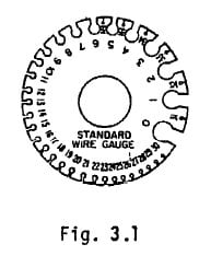
For specific capacity of a wire in a specific case check manufacturer specifications. Also check the local electrical code to see if it has stricter requirements. The size of a particular wire should be marked on the cable. It can be measured with a wire gauge. A wire gauge is shown in Fig. 3.1. The widths of the openings on the rim correspond to diameters of wires whose numbers are opposite the openings.
CONDUCTOR INSULATION
All conductors used for residential wiring must be insulated. There are several types of insulation in standard use. The most common is thermoplastic insulation, which is called "Type-T". "Type-R" means a rubber or rubber compound insulation. The letters W or H following the type, indicate moisture resistant or heat resistant insulations and can be used in wet or hotter than usual locations. Thus Type-RW or type-TW can be used in wet locations; Type-THW or Type-RHW can be used in hot and wet locations; etc.
CABLES
For many purposes it is desirable to have two or more wires grouped together in the form of a cable. This is easy to install, especially when used to wire a building that was completed before the wiring is installed, for the cable lends itself well to being fished through wall spaces. All wires are marked with the size of the conductor and the type letters indicating its insulation. A cable made up of two size 14 conductors, is marked 14-2, or one with three size i2 conductors is marked 12-3, etc. The insulation type is marked on the conductor insulation and the cable type is marked on the cable sheath.
Fig. 3.2
NON-METALLIC SHEATHED CABLE
This cable consists of two or three Type-T or Type-R wires bundled together. . It costs less than other types of cable, is light in weight and very simple to install; no special tools are needed. There are two types, they are called Type-NM and Type-NMC. The first is for use in dry locations and the second is enclosed in a plastic sheath and is suitable for use in wet locations.
ARMORED CABLE
This type of cable is commonly called BX cable. It is two or three conductors of Type-T or Type-R sheathed in a spiral galvanized armor, and called Type-ACT or Type-AC respectively. The armored cable can be used in most any location that is not considered damp; there is no armored cable for use in wet locations. In such locations the use of a lead shielded cable similar to Type-NM in construction is used.
UNDERGROUND CABLE
There are two types of underground cable, Type-UF and Type-USE. These types are for underground feeders and underground service entrances. There are Type-UF cables that also meet the requirements for Type-NM. These will be marked UF-NMC. There are many other types of cable, Suited to specialty uses. These are described in the references.
COLORING OF CONDUCTORS
Conductors, separate and in cables, come in various colors, and there is a purpose for this. Only white wire may be used for the grounded neutral wire in wiring. White wire may be used when ungrounded only for feeding power to switches when cable is being used. Other wires may be any color except white or green. They occur in the following combinations: P-conductor White, Black, 3-conductor White, Black; Red 4-conductor White, Black, Red, Blue 5-conductor White, Black, Red, Blue, Yellow
WIRE HANDLING TECHNIQUES
INSULATION/STRIPPING
To connect a cable or wire in a circuit the insulation at the ends of the wire must be removed. A hacksaw is used to cut the armor on Type-AC cable. The cut is made diagonally across the sheath, cutting just one section of the spiral. The armor is then twisted off the end. To protect the conductors from the sharp edges a fiber bushing is installed between the wires and the sheathing. Type-NM cable requires a knife to remove the sheathing. A cable should have about 8 inches of sheathing removed, but care should be taken not to hurt the conductor insulation. A knife is then used to remove the insulation from the ends of the conductors, without nicking the conductor.
SPLICING
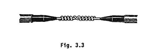
Two wires can be connected together using a splice. The most common splice is the Western Union splice shown in Fig. 3.3. It makes a good electrical contact and is strong mechanically.
Fig. 3.3
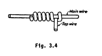
A tap splice is used to connect one wire in the middle of another, as shown in Fig. 3.4.
Fig. 3.4
SOLDERING
Soldering is the bonding of two conductors together with molten solder. This makes a low resistance path for current. The steps in soldering: 1. Clean the wires to be soldered. 2. Splice the wires. 3. Clean the finished splice. 4. Heat the splice until the wires will melt the solder. 5. Apply the solder, allowing it to melt and flow through the splice. 6. releave the heat and allow the splice to cool. This procedure allows the solder to make a chemical bond with each of the wires. This bonding operation will be hindered if the wires or the soldering iron are not clean. Many solders contain a flux which prepares the wires for the bonding. Only the rosin flux should be used for electrical wiring, as the others tend to corrode the connection. The best solder for electrical connections if 60% tin--40% lead, rosin core solder.
Fig. 3.5
TAPING
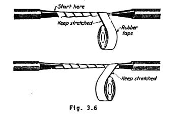
Splices should be taped after soldering to insulate the conductor. Plastic tapes are readily available and are the best to use for this purpose. The tape should be wound around the wire diagonally and progress down the splice. This should be repeated in the other direction, and back and forth until the taped splice is the same diameter as the wire.
Fig. 3.6
SCREW TERMINALS
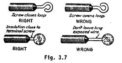
Most switches, and plugs have screw a screw terminal outlets, fuse terminal is shown holders, connections. in Fig. 3.7. circuit The breakers connection loop should and appliance of a wire be formed to in the wire before it is placed around the screw. When the loop is placed around the screw it should be placed so that the tightening of the screw tends to close the loop, rather than open ft.
Fig. 3.7
SOLDERLESS CONNECTORS
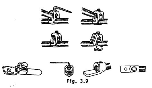
There are many types of connectors for joining wires that do not require soldering. These all depend upon pressure between the wires to insure a good electrical contact. It is difficult to heat the larger sizes of wire, and this nukes soldering difficult or entirely impossible. On larger sites of wire solderless connectors must be used. Fig. 3.8 and Fig. 3.9 show several types of solderless connectors.
Fig. 3.8
Fig. 3.9
TYPES OF SERVICE
There are several types of service that can be supplied to a consumer from the distribution or secondary lines of the system. They are: 1. 3 wire three phase (delta connection) 2. 4 wire three phase (wye connection) 3. 3 wire single phase 4. 2 wire single phase The three wire three phase service is rarely used as it provides only one voltage. The 4 wire three phase service provides three phase power at 208V. and also provides 120 V. single phase power. When three phase power is to be provided, a 4 wire service is usually the most practical. To obtain this from the three wire distribution lines, three transformers are used. The primaries of these transformers are connected in delta, and the secondaries of the transformers are connected in wye, with the neutral wire grounded. Three wire single phase service is the basic single phase service. It is obtained from the distribution lines using one transformer as illustrated in Fig. .3.10.
Fig 3.10
The 3 wire service provides two voltages. When a building requires only the lower voltage and no expansion of service is anticipated a 2 wire service can be installed using just the neutral and one of the single phase lines. In any service that uses a neutral line the neutral line must be grounded for safety.
SERVICE ENTRANCE
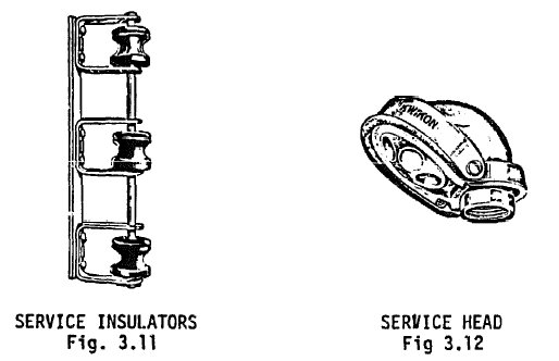
The term service entrance describes several pieces of equipment and their interconnection. The components of a service entrance are: 1. The service drop 2. The service insulators 3. The service head 4. The service entrance conductors 5. The meter 6. The building entrance 7. The main switch 8. The main over current protection 9. The service ground
THE SERVICE DROP
The service drop is the connection of the house system to the distribution system. This is done after the house installation is completed and tested, and is performed with the main switch open. The connection is made at the distribution system by removing the insulation on the secondary wires and making a tap splice, using solderless connectors. The service drop conductors are secured to an insulator rack on the pole, and strung to the service drop insulators and then connected to the conductors entering the service head. The service head should either be higher than the service drop, or there should be drip loops to prevent water from entering the service head.
SERVICE INSULATORS SERVICE HEAD
Fig. 3.11 and 3.12
THE SERVICE INSULATORS
These insulators are for securing the service drop to the resistance. They should be mounted high enough on the building to allow ten feet of clearance between the service drop and the ground. They should be mounted on a secure structure of the building or on a mast or pole installed for the purpose.
THE SERVICE HEAD
This is a unit which is mounted on the top of the conduit or cable leading to the meter. Its purpose is to prevent rain from entering the conduit or cable. It should be mounted above the service insulators so that any rain will drip down the conductors and away from the service head.
THE SERVICE ENTRANCE CONDUCTORS
These include the cable from the service head, or the conductors in the conduit, to the meter and the conductors (in cable or conduit} from the meter to inside the building and to the main switch. They should be of large enough size to safely carry the current that the system will demand. Future expansions of the house loads should be considered when sizing these conductors so that the service entrance conductors will still be adequate after expansion.
THE METER
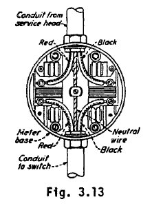
The Meter should be supplied by the co-op. The meter must match the type of service being provided. If the service is just 220 V. then a meter for 220 V. should be used. If the service is for 220/440 then a 440 V. meter should be used. If the service is three phase, then a three phase meter must be provided. Most meters come with the wiring done internally and for connection all that is required is to connect the ungrounded lines in series through the connections to the meter, as in Fig. 3.13.
Fig. 3.13
THE BUILDING ENTRANCE
Whether cable or conduit is used for the service conductors they must be sealed from the weather while outside of the building and at the entrance to the building, so that no rain can enter, and possibly cause shorting of the conductors at the main switch or panel box.
MAIN SWITCH
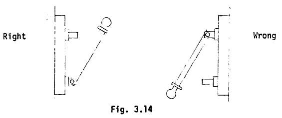
There must be a main switch for the house system. It is necessary for disconnecting the system from the power when there is work to be done on the main fuse box or feeders of the system. This switch must be rated at the same ampacity as the service entrance conductors. If knife switches are used, they must be installed so gravity will not tend to close them.
Fig. 3.14
MAIN OVER CURRENT PROTECTION
There must be fuses or circuit conductors of the service entrance switch. Never fuse a rounded breakers in chance, after conductor, series passing if that with through fuse the un the should grounded main blow there would be no ground for the entire system and severe damage could result to the equipment of the house system. If circuit breakers are used for this function they may take the place of the main switch.
THE SERVICE GROUND
If there exists an underground water system, the installation of a system ground is easily accomplished, If there are pipes that extend underground for a distance greater than 10 feet, the system can be grounded by connecting the neutral wire at the main switch to this piping system. There should be jumpers over the pipe connections between where this connection is made and where the pipe enters the ground.
If there is no underground water system, then an electrode must be driven into the ground for the purpose. This electrode can be a piece of galvanized water pipe or preferably a copper rod, of 3/4 in. or l/2 in. diameters respectively. This rod must extend at least 8 feet into the ground.
There should be no soldered joints anywhere in the service entrance or ground, because soldering of the larger conductors is a very tricky skill. Solderless pressure connections should be used instead.
EQUIPMENT SPECIFICATION
The rating of the service entrance components must be considered before installation. Determination of the total requirements of the house is covered later in this section. This determination will indicate the maximum current that will be supplied to the system. The components of the service entrance handle all of this current and must be at least large enough to handle this maximum current. The conductors, main switch, and service ground must be able to safely handle this maximum current. The main fuses should be chosen to protect the components of the service entrance which have the smallest ratings.
SWITCH BOXES, FUSES AND CIRCUIT BREAKERS
In any installation there must be a main disconnect switch. This is necessary to allow servicing of the installation without the danger of shock. A switch box wilt allow for the disconnection of individual circuits so that they may be worked on with safety.
Fuses or circuit breakers are required on any branch circuit. They must be of a size no larger than the capacity of the conductors of that branch. They are needed primarily as fire protection in case of overload or short circuiting. They also protect the installation itself, by disconnecting the circuit before it can become so hot as to start a fire or the voltage drop become so great that equipment is damaged.
CONNECTION OF SWITCH BOXES AND FUSEBOXES
Switch boxes and fuse boxes are designed with a tommu buss for connecting all of the neutral or ground wires to. These wires must all be white. The fuse sockets, the circuit breakers, or switches must be connected in series on the "hot" lines only. NEVER fuse or switch a grounded or neutral conductor.
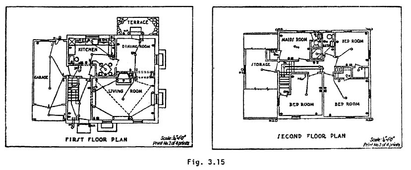
Fig. 3.15
ELECTRICAL SYSTEM LAYOUT
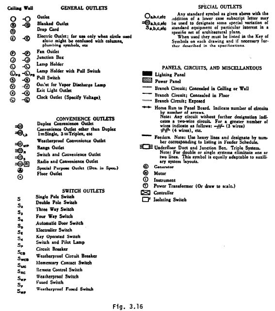
Fig. 3.15 shows an example of a house layout sketch with the layout of the electrical system indicated. You will note that the switch connection is indicated by solid or dotted lines, this denotes wiring through the walls and ceiling, or beneath the floor respectively. Other connections are not indicated shows the on the layout, but are indicated on the wiring schedule. Fig. 3.16 symbols used in house layout plans.
Fig. 3.16
LIGHTING OUTLETS
It is difficult to specify required locations for lighting outlets. There are many ways to light a room. In general, each room or area should be given a source of general lighting. This might be a ceiling fixture, several wall fixtures, or a continuous strip. In a living room or similar area the general lighting may be provided by portable units, floor and table lamps, etc., In each room, the general lighting source should be provided with control by a wall switch at the main entrances to the room. This could be done using split outlets in a living room area , where the top of each double outlet is switched and the lower has power straight from the feeders. Common sense is the best guide for the location of lighting outlets. Consider the activities that take plate in a room and decide if these require special lighting. For example, in a bedroom, light would, be needed near a mirror, preferably on both sides, in a bathroom or kitchen over the sink; or in a closet where stored material must be identified. Wall light outlets are usually located 63 inches above the floor.
LOCATION OF SPECIAL PURPOSE OUTLETS
There will be areas where there is a need for a special outlet to operate a particular appliance or machine. These should be installed at two location of the machine and meet the requirements of the machine
LOCATION OF SERVICE ENTRANCE
The ideal location for a fuse box is near the center of the house, because less wire is needed to run all the circuits. The service entrance should be located as close to this location as possible. The fuse & switch and main fuses should be just inside of the entrance of the service conductors. If the circuit fuses are located more centrally, then wire of size equal to the service conductors should be run from the main fuses to this panel box.
SAFETY
In planning the location of the various components and circuits, remember to avoid areas that would require installation in damp locations, or where the equipment or installation would be a hazard to the occupants.
INSTALLATION
JUNCTION BOXES
All outlets are installed in metal junction boxes. These have knock out slugs, which allow for entrance of the cable. All junction boxes must be securely fastened to the galls or ceilings. They are secured with wood screws to the studs or some other secure structural support. After the junction boxes are installed, the cable is run to the boxes,
SWITCH OPERATION
A switch of any type is a device for the opening or closing of a circuit. Some switches operate between several conductors, others just two. The switching of any circuit must never allow interruption of a grounded or neutral wire (white). The white or neutral wire always runs without interrupt fan by a switch, fuse or other device, up to each Point where current is to be consumed.
SINGLE POLE SWITCHES
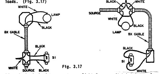
When it is desired to control a light or group of lights, an outlet or group of outlets, from one switching point a single pole switch Is used. It is wired in series with the ungrounded (black) wire feeding the load. If there are to be several loads controlled by the one switch, the switch is in series with the parallel connected loads. (Fig. 3.17)
Fig. 3.17
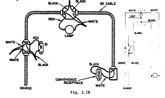
Often it is desired to operate one load continuous current to an outlet further along the same circuit Fig, 3.18 illustrates such.
Fig. 3.18
THREE-WAY SWITCHES
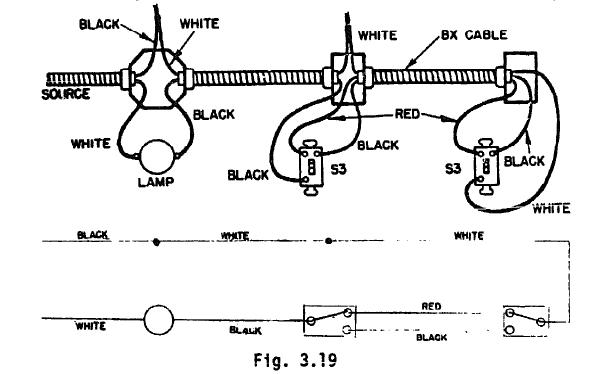
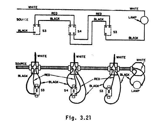
When it is desired to operate a load (or several in parallel) from two switch locations a three-way switch is used. The wiring is illustrated in Fig. 3.19. It must be remembered that this wiring must not interrupt the grounded or neutral (white) wire, from the source. Thus the wiring involves only the "hot" wire, (black). Note that in Figs. 3.17, 3.18, and 3.19 that although a white wire is run to the switch, it is an extension of the "hot" wire (black).
Fig. 3.19
FOUR-WAY SWITCHES
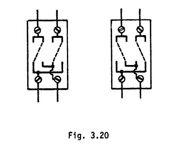
Four-way switches are used with two three-way switches to control a load (or several loads in parallel) from more than two locations. A four-way switch is pictured below:
Fig. 3.20
Fig. 3.21
Note that the white or grounded wire always connects directly to the load, with one exception. The exception is using cable in switch loops where cable runs to the switches. In this case the black wire must be used between the switch and the load, the white wire between the branch feeder wire and the switch.
LOCATION OF CONVENIENCE OUTLETS
Outlets are normally located about 12" above the floor level. They should be placed near (2 or 3 feet) corners of rooms rather than in the center of the wall to lessen the chance that they will be blocked by large pieces of furniture. They also should be installed at locations where there is an expected demand.
LOCATION OF WALL SWITCHES
Wall switches should be installed about 48" above the floor level on the latch side of the doorway, within the same room as the lights it controls.
MULTIPLE SWITCH CONTROL
Any room or area with more than one entry should have multiple switch control, i.e. using 3-way and possibly 4-way switches. There should be a switch at each entrance. the fastener attached to the cable and the cable and fastener connected to the box. The cable is prepared for wiring to the outlet or switch by removing about six inches of the outer covering from the cable and removing about 3/4 in. of insulation from each conductor. Then the fastening clamp is attached at the paint where the outer cover ends. If there is a grounding wire in the cable, it should always be connected to the junction box.
OUTLETS
Lighting and appliance outlets are manufactured with a color coding There are two screw terminals for the attachment of the conductors. One screw is a whitish colored nickel, and the other is the standard brass color. The ground or neutral wire (always white) is connected to the whitish colored screw. The "hot" wire, which should usually be black, is connected to the brass screw. If there is a third, green connecting screw, this should be connected to the grounding wire of the cable, or to the junction box, which has been grounded.
SWITCHES
Switches are not cola, coded at the connecting terminals, because they are always connected in series with the "hot" lines. Therefore the terminals on a switch are brass. Switches and outlets art? connected, installed in the box, and covered with a plate that protects the consumer from contact with any of the conductors.
SPLICES
All splices made on the cables must be placed in junction boxes. This prevents the possibility of the splice being pulled apart, since the cables are securely fastened to the box. Any connections that are not made to the terminals of a switch, outlet or lamp fixture must be taped or otherwise insulated.
DROP CORDS
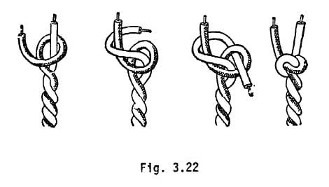
When wiring a drop cord ceiling outlet, an underwriters knot should be tied in the cord to prevent pulling on the connections. This knot should also be used when wiring any plug for an appliance.
Fig. 3.22
"NEW" AND "OLD" WORK
"New" work is the installation of a system in a house while under construction. "Old" work is the installation of a system in a completed house. Most of the work that will be encountered in the electrification project will be "old" work. Any concealed wiring will have to be installed in covered over areas. If allowable, surface wiring techniques will be most economical. This requires the use of Type NM or Type NMC cables, surface raceway, surface conduit, or open knob and tube work.
NM OR NMC SURFACE WIRING
With must any wood frame, or similar construction, the installation of surface NM type cable is a matter of securing the cable to the wood supports of the house. Care must be taken in running the cable, to protect it from damage, that is to keep it flush against the surface and avoid areas that will subject it to injury. This is done with straps, or staples, leaving the insulation unharmed. There should be a strap or staple every 3 feet and within 12 inches of a box.
OPEN KNOB AND TUBE WORK
Knob and tube work is very little used today. It has been almost entirely replaced by non-metallic sheathed cable. It is a wiring system using only single insulated conductors, which are run on the surface and supported by insulating knobs or cleats and when passing through holes in walls or studs, are enclosed in insulated tubes. These knobs and tubes are usually porcelain. This method is only practical when insulators and single conductors are economically available, while cable is prohibitive in price.
SURFACE RACEWAYS
Although this method is seldom seen in residences, it is a very useful method of protecting wiring done on the surface. A raceway consists of two pieces, one that Is fastened securely snaps on like a cover. The number of conductors through a raceway depends upon its size. to the wall and that may be the other one.
ARMORED CABLE (METAL CLAD CABLE)
Type-AC or Type MC cable can also be used for surface wiring, and allows for good protection of the conductors from physical damage. It is secured by staples or straps, in such a way as to avoid damage to the sheathing. It cannot be used in damp locations. The type that is usable in damp or other destructive situations, has a lead sheathing just inside the spiral armor. It is called Type ACL.
GENERAL
For all of these wiring methods, metal boxes are required for mounting the switches, outlets, lamp sockets, etc. Any splicing of wire must be done in a metal box and not in the raceways, conduits or in the open, except for knob and tube work where there must be support within 12" on both sides of the splice or tap, and the splice must be taped.
CONCEALED OLD WIRING
Old wiring that is concealed requires much extra effort in the installation. Holes must be carefully cut in the walls for the installation of the outlet boxes, and wires or cables must be fished through the spaces in the walls. Extra holes have to be drilled to allow for the cables to pass through hidden obstructions. The techniques required for concealed old work are described fn:
MOTOR SELECTION
Motors are not rated in watts as are other electrical loads, they are rated in horsepower. This is because motors consume electrical power in proportion to the amount of power they are
