Note: This page describes the mechanical build and software installation. Please refer to the paper for the electronics.
Note: This page describes the mechanical build and software installation. The paper describes the electronics as it was originally implemented. This method is not maintained anymore. It is now recommended to use a 3-D printer controller such as a RAMPS or Melzi and [[Franklin]] to control the device. The old method is detailed in the Discussion tab of this page.
{| style="margin:auto;"
{| style="margin:auto;"
Line 43:
Line 43:
{|class="wikitable" style="margin:auto"
{|class="wikitable" style="margin:auto"
|+Materials
|+Materials
!Description
!3-D Printed
!Count
!Count
|-
|-
Line 52:
Line 52:
|1
|1
|-
|-
|Plunger Holder base and tab
|Plunger Holder base
|1
|-
|Plunger Holder tab
|1
|1
|-
|-
Line 60:
Line 63:
|Idler End
|Idler End
|1
|1
|-
!Motors & Metal
!Count
|-
|-
|NEMA17 motor
|NEMA17 motor
Line 88:
Line 94:
|5
|5
|-
|-
|M5 threaded rod
|M5 threaded rod 0.2 m
|0.2 m
|1
|-
|-
|6mm A2 tool steel
|6mm A2 tool steel 0.2 m
|0.4 m
|2
|}
|}
|
|
Line 106:
Line 112:
{{clear}}
{{clear}}
==Procedure==
==How to Build an Open-source Syringe Pump==
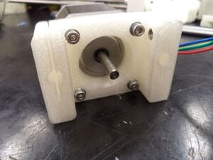
#[[File:MOST_step01.JPG|thumb|right|Motor end mounted to motor.]]Secure motor into the motor end using 4 M3 washers and 4 M3 x 20mm socket head cap screws.{{clear}}
#[[File:MOST_step01.JPG|thumb|right|Motor end mounted to motor.]]Secure motor into the motor end using 4 M3 washers and 4 M3 x 20mm socket head cap screws.{{clear}}
Line 122:
Line 128:
#[[File:MOST_step13.JPG|thumb|right|Mounted syringe.]] Insert the tab of the plunger holder on top of the plunger to secure it to the pump and prevent slipping when in use. {{clear}}
#[[File:MOST_step13.JPG|thumb|right|Mounted syringe.]] Insert the tab of the plunger holder on top of the plunger to secure it to the pump and prevent slipping when in use. {{clear}}
==Controller: Connection and Calibration==
This is a description for using [[Franklin]] to control the device. Latest version available for free [https://github.com/mtu-most/franklin Github].
==Controller: Connection and Calibration==
(The paper describes the electronics as it was originally implemented. This method is no longer maintained. It is now recommended to use a RepRap 3-D printer controller such as a RAMPS or Melzi, which you can pick up online and Franklin to control the device. The original instructions are available in the Discussion tab.)
The motor must be connected to the control board on the terminals that are intended for the first axis (normally called X). In Franklin, load the profile for the board you have, then set up the profile and calibrate the pump:
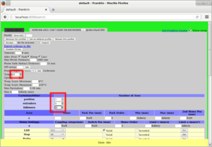
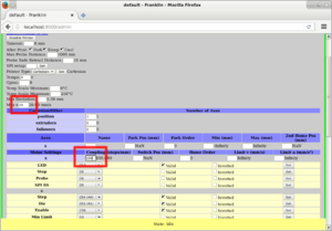
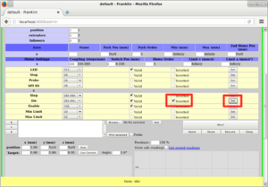
#{{clear}}[[File:MOST_pump01.png|thumb|right|Set the nuber of temps to 0, position axes to 1, and extruders and followers to 0.]]Set the nuber of temps to 0, position axes to 1, and extruders and followers to 0.
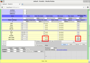
#{{clear}}[[File:MOST_pump02.png|thumb|right|Disable both limit switches.]]Disable both limit switches.
#{{clear}}[[File:MOST_pump03.png|thumb|right|Set the coupling to 100 step/mm and the speed limit to 20 mm/s.]]Set the coupling to 100 step/mm and the speed limit to 20 mm/s.
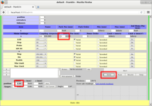
#{{clear}}[[File:MOST_pump04.png|thumb|right|Home the pump.]]Set the switch position to 0, then home the pump. This sets the current position to the switch position.
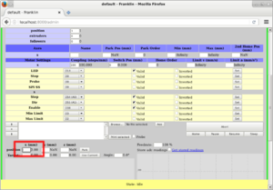
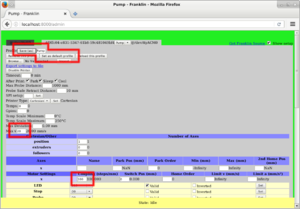
#{{clear}}[[File:MOST_pump05.png|thumb|right|Select the x position input.]]Select the x position input. Then press arrow up and down to move the pump in small steps page up and down to move it in larger steps.
#{{clear}}[[File:MOST_pump06.png|thumb|right|Change the direction, if required.]]The pump should push liquid out when moving in the positive direction. If it is moving in the wrong direction, invert it.
#{{clear}}Pull the syringe out slightly past a big marker. Then using tiny steps, push the syringe to the bigger marker so the plunger is exactly on the mark. (Because of backlash, you want to do the entire procedure with pushing only.)
#Click the home button to set the position to 0.
#Push it further until you reach another marker (larger distance is better). Make sure to do small steps at the end, in order to make sure you do it by pushing only.
#Record the current position.
#Divide the reported number of mm times the coupling by the number of milliliters between the markers. This is the correct Coupling value for this syringe.
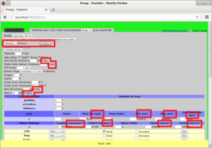
#{{clear}}[[File:MOST_pump07.png|thumb|right|Save the profile.]]After setting the correct coupling, adjust the maximum speed to a value that works (if it is too high, the motor will skip) and name and save the profile. Also set this profile as default.
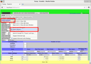
#{{clear}}[[File:MOST_pump08.png|thumb|right|Export the profile.]]Right-click on the export link and save the target to a location on your computer where you can find it. Use this file to restore the profile if you need it.
#{{clear}}[[File:MOST_pump09.png|thumb|right|Change the units.]]If you want the interface to be correct (of course you do), open the profile in a plain text editor and change the unit_name setting from mm to mL. Save it and import the new settings. Note how all the units in the interface change.
{| style="margin:auto;"
|- style="vertical-align:top;"
|[[File:MOST_calibration_materials.JPG|thumb|400px|alt=Necessary tools|Items to connect and control the syringe pump.]]
{|class="wikitable" style="margin:auto"
|+Controller
|-
|two ethernet cables
|-
|raspberry pi (case optional)
|-
|micro-USB adaptor cable
|-
|wireless router
|}
|}
{{clear}}
{{clear}}
The pump is now ready to use. You can use the x position entry to move it manually, or upload G-Code which moves the X coordinate to move it in a pre-programmed pattern. A simple G-Code example is:
#If you have previously done a manual install: remove /usr/local/sbin/pump-server and the line referencing it in /etc/rc.local from the Raspberry Pi.
<nowiki>
#Install on the Raspberry Pi the packages python-fhs, python-network, python-websockets and pump-server, all from [http://wijnen.dtdns.net/archive/stable/all/].
G91 ; Use relative positioning.
#Shut the Pi down.
G1 X10 F600 ; Push 10 mL at 600 mL/min (10 mL/s).
#[[File:MOST_cal01.JPG|thumb|right|Motor plugged into raspberry pi.]] Plug the motor into the raspberry pi. If the motor is plugged in the wrong way the pump will push when it is told to pull, so then you will want to turn the plug around. '''NOTE: Do not plug and unplug the motor from the pi if the pi is plugged in to a power source. ''' {{clear}}
G1 X1 F120 ; Push 1 mL at 100 mL/min (2 mL/s).
#[[File:MOST_cal02.JPG|thumb|right|Micro-USB plugged into raspberry pi.]] Using a micro-USB adaptor plug the raspberry pi into the computer. {{clear}}
G4 P500 ; Wait 500 ms.
#[[File:MOST_cal03.JPG|thumb|right|Raspberry pi hooked up to router.]] Plug an ethernet cable into the raspberry pi, then connect it to the router. Then connect the router to the computer with another ethernet cable. {{clear}}
G1 X1 ; Push another mL at the same speed.
#Plug everything into an outlet and turn on the router. Look to see that your computer recognizes the network. Once it does, switch over to that network and open up your web browser. Type in the address bar: '''pi.local:8080'''. ''NOTE: This is only the address if a version of Linux is in use. We have no practical way to get the address on Windows or Mac, however it does work on Windows and Mac if the name can be obtained. Most routers have an administration web site which can list current clients. Consult your router manual for how to get this information.''
G1 X10 F600 ; Repeat.
#[[File:MOST_cal05.JPG|thumb|right|Raspberry pi hooked up to router.]]The site that is now opened is the pump control interface.
G1 X1 F120
#Set the Calibration to 1 ml/mm and set the speed to 1 ml/s.
G0 X-5 ; Pull back 5 mL at maximum speed.</nowiki>
#Pull the syringe out slightly past a big marker. Then using tiny steps, push the syringe to the bigger marker so the plunger is exactly on the mark. (Because of backlash, you want to do the entire procedure with pushing only.)
#Set the position to 0 ml.
== Minimum Pump Rate==
#Push it further until you reach another marker (larger distance is better). Make sure to do small steps at the end, so you do it by pushing only.
The minimum pump amount is a single step of the motor; how much that is depends on the size of the syringe. Here the lead screw has a pitch of 0.8mm and the motor does 3200 microsteps per revolution, so one step is a plunger movement of 0.8mm/3200=250nm. The cross section of a 25ml syringe is around 4cm², so one step is the product of those, which is 0.1mm³=0.1μL.
#Record the current position. The unit of this position is really mm, because a calibration value of 1 ml/mm was used.
#Divide the number of milliliters between the markers by the number of millimeters you pushed it. This is the correct calibration value for this syringe.
There is no minimum value for the speed that the pump can go, but if you get near the step size, the flow will be in noticeable steps instead of continuous. For example, if you want 1μL/min, it will do one step every 6 seconds.
==See also==
==See also==
Line 167:
Line 177:
* [[Open-source hardware]]
* [[Open-source hardware]]
* [[Syringe pump literature review]]
* [[Syringe pump literature review]]
* [[Open Source 3-D Printed Nutating Mixer]]
* [[3-D printable open source dual axis gimbal system for optoelectronic measurements]]
* [[Ystruder: open source multifunction extruder with sensing and monitoring capabilities]]
* [http://www.thingiverse.com/thing:1413969 Bricoleur Clay Extruder, Open Source]
==In the News==
==In the News==
[[image:emilypump.jpg]]
* [http://www.mtu.edu/news/stories/2014/september/science-just-got-cheaper-and-faster-design-library-lets-researchers-print-their-own-syringe-pumps.html Science Just Got Cheaper (and Faster): Design Library Lets Researchers Print their Own Syringe Pumps] - Michigan Tech News
* [http://www.mtu.edu/news/stories/2014/september/science-just-got-cheaper-and-faster-design-library-lets-researchers-print-their-own-syringe-pumps.html Science Just Got Cheaper (and Faster): Design Library Lets Researchers Print their Own Syringe Pumps] - Michigan Tech News
* [http://gizmodo.com/doctors-could-3d-print-their-own-tools-for-a-fraction-o-1636053997 Doctors Could 3D Print Their Own Tools For a Fraction of the Cost] - Gizmodo, [http://www.gizmodo.in/science/Doctors-Could-3D-Print-Their-Own-Tools-For-a-Fraction-of-the-Cost/articleshow/42755979.cms Gizmodo India], [http://www.gizmodo.com.au/2014/09/doctors-could-3d-print-their-own-tools-for-a-fraction-of-the-cost/ Gizmodo Australia], [http://www.dailynewsen.com/technology/doctors-could-3d-print-their-own-tools-for-a-fraction-of-the-cost-h2650866.html USA News]
* [http://gizmodo.com/doctors-could-3d-print-their-own-tools-for-a-fraction-o-1636053997 Doctors Could 3D Print Their Own Tools For a Fraction of the Cost] - Gizmodo, [http://www.gizmodo.in/science/Doctors-Could-3D-Print-Their-Own-Tools-For-a-Fraction-of-the-Cost/articleshow/42755979.cms Gizmodo India], [http://www.gizmodo.com.au/2014/09/doctors-could-3d-print-their-own-tools-for-a-fraction-of-the-cost/ Gizmodo Australia], [http://www.dailynewsen.com/technology/doctors-could-3d-print-their-own-tools-for-a-fraction-of-the-cost-h2650866.html USA News]
Line 213:
Line 229:
* [http://www.electronicosonline.com/2014/10/27/cientificos-ahorran-millones-en-equipo-con-simple-invento/ Científicos ahorran millones en equipo con simple invento] - Electronics Online (Spanish)
* [http://www.electronicosonline.com/2014/10/27/cientificos-ahorran-millones-en-equipo-con-simple-invento/ Científicos ahorran millones en equipo con simple invento] - Electronics Online (Spanish)
* [http://3dprintingindustry.com/2015/02/02/3d-printed-open-hardware-syringe-pump-value-800m/ 3D Printed Open Hardware Syringe Yields $800M Value, Study Finds]- 3D Printing Industry
* [http://3dprintingindustry.com/2015/02/02/3d-printed-open-hardware-syringe-pump-value-800m/ 3D Printed Open Hardware Syringe Yields $800M Value, Study Finds]- 3D Printing Industry
If you are customizing your own pump you will need MOST SCAD library files found here: https://github.com/mtu-most/most-scad-libraries Download them all and put them in the same folder as the files for the pump -- then the SCAD will compile correctly.
See also: Lynch open source syringe pump modifications - includes 1) Escape mechanism to move pusher block without running the motor, 2)Open syringe clamp to allow easy removal, 3) Arduino Control with EasyDriver.
This article explores a new open-source method for developing and manufacturing high-quality scientific equipment suitable for use in virtually any laboratory. A syringe pump was designed using freely available open-source computer aided design (CAD) software and manufactured using an open-source RepRap 3-D printer and readily available parts. The design, bill of materials and assembly instructions are globally available to anyone wishing to use them. Details are provided covering the use of the CAD software and the RepRap 3-D printer. The use of an open-source Raspberry Pi computer as a wireless control device is also illustrated. Performance of the syringe pump was assessed and the methods used for assessment are detailed. The cost of the entire system, including the controller and web-based control interface, is on the order of 5% or less than one would expect to pay for a commercial syringe pump having similar performance. The design should suit the needs of a given research activity requiring a syringe pump including carefully controlled dosing of reagents, pharmaceuticals, and delivery of viscous 3-D printer media among other applications.
Note: This page describes the mechanical build and software installation. The paper describes the electronics as it was originally implemented. This method is not maintained anymore. It is now recommended to use a 3-D printer controller such as a RAMPS or Melzi and Franklin to control the device. The old method is detailed in the Discussion tab of this page.
Parts for syringe pump assembly.
Materials
3-D Printed
Count
Motor End
1
Carriage
1
Plunger Holder base
1
Plunger Holder tab
1
Body Holder
2
Idler End
1
Motors & Metal
Count
NEMA17 motor
1
5mm x 5mm shaft coupling
1
625z ball bearing
2
LM6UU linear bearing
2
M3 x 10mm socket head cap screw
6
M3 x 20mm socket head cap screws
4
M3 x 40mm socket head cap screws
4
M3 hex nut
13
M5 hex nut
5
M5 threaded rod 0.2 m
1
6mm A2 tool steel 0.2 m
2
Necessary tools for assembling syringe pump.
Tools
M3 allen key
3mm drill bit
How to Build an Open-source Syringe Pump
Motor end mounted to motor.Secure motor into the motor end using 4 M3 washers and 4 M3 x 20mm socket head cap screws.
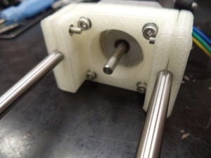
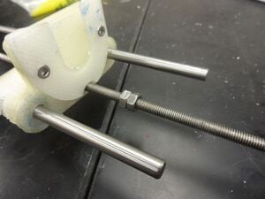
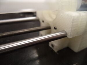
Metal rods inserted in motor end.Insert the 2 metal rods into motor end, then secure them in place with 2 M3 nuts and 2 M3 x 10mm socket head cap screws.
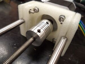
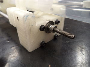
Threaded rod coupled to motor. Insert threaded rod into the coupler halfway, the other half should be on the motor, secure it.
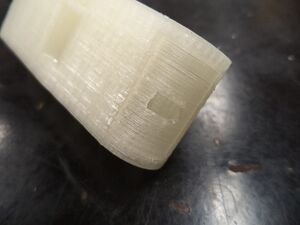
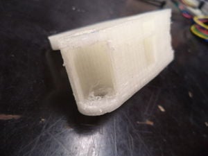
Not hollowed-out carriage.Hollowed out carriage.Hollow out the two ends of the carriage, with a handheld drill bit or knife to make a hole in the plastic.
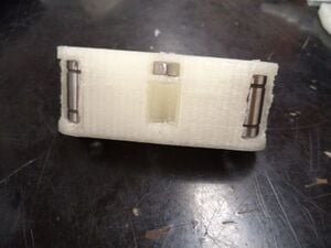
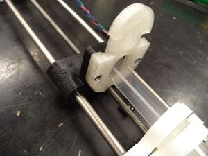
Linear bearings and nut inserted in the carriage. Snap the linear bearings into place on the hollowed out ends of the carriage. Then insert an M5 nut into the nut-trap on the bottom of the carriage.
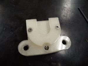
Base of the plunger holder attached to carriageAttach the base of the Plunger holder to the carriage with 2 M3 nuts and 2 M3 x 10mm socket head cap screws.
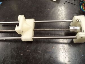
Carriage threaded onto the rods. Slide the carriage onto the threaded rod and make sure the two metal rods fit into the linear bearings.
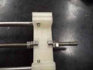
M5 nutes mounted on threaded rod. After the carriage is midway down the threaded rod, thread two M5 nuts onto the threaded rod.
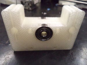
Bearings inserted into the idler end. Insert the two bearings into the circular slots in the idler end.
Idler end mounted on the rods. Now slide the idler end onto the rods and secure it with two more M5 nuts on the end of the threaded rod. Push the two nuts already on the rod up to the idler end to secure it.
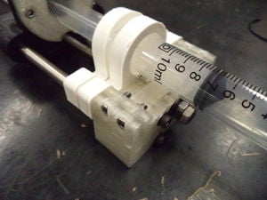
Syringe in the body and plunger holders. Insert the syringe body into the body holders, then slide the plunger into the base of the plunger holder.
Syringe in the body and plunger holders.Syringe in the body and plunger holders. Using four M3 x 40mm bolts, four M3 washers, and four M3 nuts secure the two holding pieces to the idler end of the pump. Put two nuts it the top of the holder closer to the carriage and two nuts in the bottom of the holder against the idler end.
Mounted syringe. Insert the tab of the plunger holder on top of the plunger to secure it to the pump and prevent slipping when in use.
Controller: Connection and Calibration
This is a description for using Franklin to control the device. Latest version available for free Github.
(The paper describes the electronics as it was originally implemented. This method is no longer maintained. It is now recommended to use a RepRap 3-D printer controller such as a RAMPS or Melzi, which you can pick up online and Franklin to control the device. The original instructions are available in the Discussion tab.)
The motor must be connected to the control board on the terminals that are intended for the first axis (normally called X). In Franklin, load the profile for the board you have, then set up the profile and calibrate the pump:
Set the nuber of temps to 0, position axes to 1, and extruders and followers to 0.Set the nuber of temps to 0, position axes to 1, and extruders and followers to 0.
Disable both limit switches.Disable both limit switches.
Set the coupling to 100 step/mm and the speed limit to 20 mm/s.Set the coupling to 100 step/mm and the speed limit to 20 mm/s.
Home the pump.Set the switch position to 0, then home the pump. This sets the current position to the switch position.
Select the x position input.Select the x position input. Then press arrow up and down to move the pump in small steps page up and down to move it in larger steps.
Change the direction, if required.The pump should push liquid out when moving in the positive direction. If it is moving in the wrong direction, invert it.
Pull the syringe out slightly past a big marker. Then using tiny steps, push the syringe to the bigger marker so the plunger is exactly on the mark. (Because of backlash, you want to do the entire procedure with pushing only.)
Click the home button to set the position to 0.
Push it further until you reach another marker (larger distance is better). Make sure to do small steps at the end, in order to make sure you do it by pushing only.
Record the current position.
Divide the reported number of mm times the coupling by the number of milliliters between the markers. This is the correct Coupling value for this syringe.
Save the profile.After setting the correct coupling, adjust the maximum speed to a value that works (if it is too high, the motor will skip) and name and save the profile. Also set this profile as default.
Export the profile.Right-click on the export link and save the target to a location on your computer where you can find it. Use this file to restore the profile if you need it.
Change the units.If you want the interface to be correct (of course you do), open the profile in a plain text editor and change the unit_name setting from mm to mL. Save it and import the new settings. Note how all the units in the interface change.
The pump is now ready to use. You can use the x position entry to move it manually, or upload G-Code which moves the X coordinate to move it in a pre-programmed pattern. A simple G-Code example is:
G91            ; Use relative positioning.
G1 X10 F600    ; Push 10 mL at 600 mL/min (10 mL/s).
G1 X1 F120     ; Push 1 mL at 100 mL/min (2 mL/s).
G4 P500        ; Wait 500 ms.
G1 X1          ; Push another mL at the same speed.
G1 X10 F600    ; Repeat.
G1 X1 F120
G0 X-5         ; Pull back 5 mL at maximum speed.
Minimum Pump Rate
The minimum pump amount is a single step of the motor; how much that is depends on the size of the syringe. Here the lead screw has a pitch of 0.8mm and the motor does 3200 microsteps per revolution, so one step is a plunger movement of 0.8mm/3200=250nm. The cross section of a 25ml syringe is around 4cm², so one step is the product of those, which is 0.1mm³=0.1μL.
There is no minimum value for the speed that the pump can go, but if you get near the step size, the flow will be in noticeable steps instead of continuous. For example, if you want 1μL/min, it will do one step every 6 seconds.
See also
Lynch open source syringe pump modifications - includes 1) Escape mechanism to move pusher block without running the motor, 2)Open syringe clamp to allow easy removal, 3) Arduino Control with EasyDriver
"Another day, another phenomenal addition to the list of practical, hype-less, real, tangible, 3D printable tools that are bound to bring on some welcome changes. This time, it’s the scientific community that can sing praises and raise their glasses as they’re about to reap the benefits – and save a bundle – on 3D printed syringe pumps."
3D打印,模型库,注射泵,开源 - 中关村在线办公打印频道 - oa.zol.com.cn (Zhongguancun Online (zol.com.cn) - the world's first Chinese technology portal, Greater China's most commercially valuable IT professional portal.)