
The problem our team identified is the level of difficulty in producing a large quantity of prints. More specifically, it is inefficient to require human intervention at the beginning and end of each print. If this problem were addressed, it would allow the operator to queue several prints, leave, and return to collect the completed prints.
Objective[edit | edit source]
To develop a simple, low cost, open source solution for automating FDM printing at the hobbyist level. Automation of a consumer grade 3D printer would include configurable software to modify G-code, part removal hardware which can be installed externally to the 3D printer without modification, and a part storage solution which could accept multiple iterations of any potential design printed with the project solution. The project will feature a few solutions designed to be simple and cost effective in order to keep the barrier to entry as low as possible. The parts sourced for the project will be 3D printed when possible, use M3 nuts, bolts, and washers, one small piece of sheet metal, and only requires two external stepper motors, couplers, and lead screws. This project would maximize the productivity of most consumer-grade 3D printer designs and would massively reduce the amount of time hobbyists waste before and after a print's execution. When completed, the solution should ideally be equal to or more reliable that the base printer model.
Background[edit | edit source]
FDM printing has revolutionized the way industry leaders, researchers, and hobbyists alike design, prototype, and manufacture new parts and products. It has granted individuals access to the same level of quality and efficiency as could only be achieved previously by more costly large-scale productions. While individuals have had access to these advantages in recent years, they have not benefited from the automation potential offered by manufacturing of this kind. Products designed and manufactured using the FDM printing process are extremely time consuming at the hobbyist level, as human intervention is required both before and after the machine's operation. If the FDM printing process were completely automated through queue, print, and removal, the productivity potential of each machine could be realized by both the hobbyist as well as the manufacturing industry.
This project started when the OSHE was asked by the university to print hundreds of husky statues that took 8 hours each to print. Instead of having to remember to come into the lab every eight hours and start a new print, it would be much easier if the process was automatic. We want the robotic arm to know when the 3D print is complete, remove the finished print, and then tell the 3D printer to begin again.
Project Significance[edit | edit source]
Project Goals:
- Add robotic arm without interfering in normal printer capabilities
- The project features a metal scraper with dual lead screws
- The design rests outside the printer's perimeter
- The printer bed's area is adequately addressed by the design
- Prints up to 75,000 mm^2 have been verified with the poptab design
- Write G-Code to clear the printer bed
- The printer is controlled using a custom dual extruder firmware version
- The design is manipulated using G-Code commands to the second printer head
- Automate G-Code generation to clear bed and queue a print
- Verify that the system works
- A time lapse of the working system can be found here, and below
Possible Future Goals:
- Add a limit switch so we can know where the scraper is
- Refine and update the python script to take advantage of upcoming features in Marlin
- Add the rail system originally intended to lead the cart
- Add a failsafe feature, in case of failed print removal
- Move the print queue user interface to the printer itself
Bill of Materials[edit | edit source]
| Quantity | Material | Est. Cost |
|---|---|---|
| 2 | 500mm T8 Lead Screw w/ nut | $38 |
| 2 | NEMA 17 Stepper Motor | $26 |
| 1 | Kg PLA filament | $25 |
| 1 | Aluminum Foil Heat Tape | $20 |
| 1 | Galvanized Steel Sheet Metal 0.6mmX200mmX500mm | $12 |
| 50 | M3x16mm Socket Bolts & Nuts (Washers Recommended) | $8 |
| 2 | 5mm to 8mm Flex Coupler | $7 |
| 1 | Teflon Lubricant | $7 |
| 4 | 14-26 AWG Wire Nuts (Recommended) | $1 |
| 4 | EL-MS0059 Female Pins (Taz 6) | $1 |
| 1 | EL-MS0062 4 Pin Female Connector (Taz 6), or equivalent | $1 |
| 10 | Feet 22 AWG Wire | $1 |
| 1 | Thick Paper Sheet 1' x 2' | $1 |
| TOTAL | $148 |
Tools needed[edit | edit source]
| Quantity | Tool |
|---|---|
| 1 | Measurement tool |
| 1 | Drill |
| 1 | Soldering iron |
| 1 | Drill bit (>3mm) |
| 1 | Metal file and/or Sanding paper (Coarse) |
| 1 | Metal saw/Tinsnips |
| 1 | Wire strippers (Recommended) |
| 1 | Wire crimpers (Recommended) |
| 1 | Bench vise (Recommended) |
Technical Specifications and Assembly Instructions[edit | edit source]
In order to begin the assembly (and design) of the project, actions should be taken to accommodate the situation accordingly. Example files will be provided, and can be modified or used as-is to meet similar design restrictions.
| Action | Part |
|---|---|
| Measure dimensions, screw holes | Stepper motor, lead screw nut |
| Measure radius | Flex coupler |
| Measure width, depth | Print bed |
| Measure width, height, thickness, shape | Printer frame |
| Measure shortest possible depth | Printer head, frame |
| Accommodate printer head (comfortably), printer frame | Lead screw plane |
| Accommodate motor shape & screws, flex coupler radius, printer frame | Left motor bracket x 1 |
| Mirror left motor bracket | Right motor bracket x 1 |
| Accommodate lead screw, printer frame, (and bearing) | Left lead screw mount x 1 |
| Mirror left lead screw mount | Right lead screw mount x 1 |
| Accommodate lead screw nut radius, screw holes, printer head, printer frame | Rail cart x 2 |
| Accommodate scraper angles while stored (avoid printer head comfortably) and deployed (scrape angle), rail carts | Left hinge mount x 1 |
| Mirror left hinge mount | Right hinge mount x 1 |
| Accommodate scraper, hinge mount geometry | Scraper clip x 2 |
| Accommodate 1/3 width of printer bed, printer head, screw holes in center | Scraper cover x 3 |
| Accommodate scraper. Optional part to prevent blade flexing, as wide as possible. | Scraper rib x 1 |
| Accommodate width of printer bed (bottom width), width of lead screw with all attachments (top width), shortest possible depth from lead screw plane to back edge of print bed (height), screw holes | Scraper x 1 |
WARNING: Read directions completely before attempting. While using any part, program, or printer for the first few times, exercise caution and restraint while maneuvering the scraper. Collisions can damage both the scraper and printer. Be ready to stop the machine at a moment's notice, and if any part is questionably placed or maneuvered, turn off the machine and verify that the intended operation was taking place and all parts are in order. Make sure the Again.py, init.txt, and iter.txt scripts have the right heights and movement commands for your printer before starting a print. This may take some trial and error to get just right.
In order to assemble, affix each printed part to the printer in the order the actions are listed (i.e. start with left motor bracket and end with scraper). Use washers on all printed surfaces to avoid crushing them, and use caution when tightening. When affixing the scraper clip to the hinge mounts, insert the nut into the bottom side of the hinge mount, and insert the bolt from the topside. Then glue the bottom side of the hinge mounts to the rail carts. If desired, accommodate screw holes to attach the hinge mounts to the rail carts. When inserting the bolts into any part of the scraper such as the scraper cover, scraper clip, or scraper rib, use caution to avoid collisions with the printer frame, printer head, or printer bed. Orient the screws properly to minimize the chance of collisions, and file the screws to an appropriate length if needed.
To wire the stepper motors, refer to the wiring and board diagrams the manufacturer has provided for the printer. The TAZ 6 files used for this project are available below. There are several potential points where a harness can be made and the dual extruder signal can be used, but for the purposes of this project the connection was made on a board inside the printer rather than the external (intended) dual extruder harness. Crimp the four necessary wires into the pins, insert into the connector, insert connector into the intended spot, and connect the loose wires to the stepper motors with the wire nuts. The wire nuts are highly recommended, as it is easiest to wire the motors through trial and error due to the variability of wiring schemes. Be sure the stepper motors are not connected to the lead screws while testing. Once both motors move in sync in the intended direction and no longer skip any steps, move on to the next part.
To move the scraper manually, use the movement feature intended for the second extruder. The scraper should be operational in manual mode for now, but a custom dual extruder firmware must be installed onto the printer before it can run autonomously. This is due to a safety feature which will not allow the extruder to move until it is up to temp. This custom dual extruder firmware for the TAZ 6 has been modified to set only the second extruder to an acceptable constant temperature. This allows the printer's safety feature for the second extruder to be worked around. Use this resource for help installing a new firmware version. ATTENTION: While the printer is running a firmware designed for a dual extruder head, it is important to note that it still only has a single extruder head. DO NOT use a dual extruder profile in any slicer, as it will attempt to manipulate the second extruder during several initialization steps throughout the print, even if it is not being used. It should be clear that this can cause major issues. Instead use a single extruder profile, as if the firmware has not been changed at all.
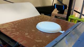
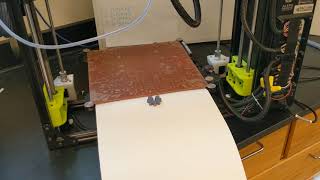
Finally, to assemble the part storage solution, begin by removing the printer bed. Tape the cardstock paper to the bottom of the bed with the aluminum heat tape and score the paper at the edge of the bed so it folds when not supported. Place printer on elevated surface, and place parts bin below the printer. Completed prints should be supported by the paper until the printer bed is not supported by the printer frame, and subsequently fall into the parts bin.
To operate the print queueing feature, simply run the Again.py program in the same directory as the dependent.txt files and the desired G-Code files before moving the completed G-Code to the file storage location intended for printing. Follow the instructions as they appear in the console. NOTE: In order for the program to operate correctly, you need to include the file extensions (e.g..gcode) and verify that the scraper moves as intended. Additionally, all of the automatic movement features present in Again.py, init.txt, and iter.txt should be tested under close supervision multiple times in a row without re-initialization.
To initialize the design, move the scraper downwards until the tip of the scraper touches the printer bed. Then begin the print. The scraper should immediately move upwards into the storage position, and the print should begin as usual. When the printer is finished, the print bed should move to the back, move the printer head all the way up, execute the temperature commands set, move the scraper to almost touch the bed, maneuver the scraper into a deployed position, and begin scraping. When the bed reaches the front, the scraper should return to the storage position, the bed should move again to the back, and the next print should continue as usual. When finished with all prints, the bed should cool to a safe temperature. Be sure to play with speeds, distances, and temperatures to achieve optimal performance with your setup.
Content[edit | edit source]
-
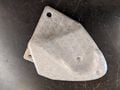
Fig 1: Scraper hinge mount.
-
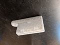
Fig 2: Scraper hinge clamp.
-
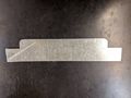
Fig 3: Scraper blade.


-
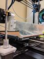
Fig 1: Scraper initialization.
-
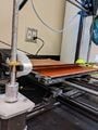
Fig 2: Scraper deployed.
-
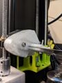
Fig 3: Hinge deployed.
-
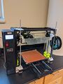
Fig 4: Scraper in storage.
-
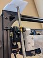
Fig 5: Scraper cart in storage.
-
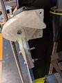
Fig 6: Hinge in storage.
-

Fig 7: Octoprint interface
-
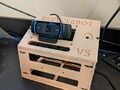
Fig 8: Octoprint webcam for monitoring


References[edit | edit source]
- General G-Code reference used for file modification: https://reprap.org/wiki/G-code/es#G0_.26_G1:_Move
- General G-Code reference: https://marlinfw.org/docs/gcode/M140.html
- Lulzbot TAZ 6 user manual: http://download.lulzbot.com/TAZ/6.01/documentation/manual/6.01/source/Manual.pdf
- Lulzbot TAZ 6 sep-by-step guide to install dual extruder and firmware: https://ohai.lulzbot.com/project/TAZ-6-dual-extruder-v2-tool-head-installation/accessories/
- Lulzbot Taz 6 vanilla firmware: https://www.lulzbot.com/Cura
- Lulzbot Taz 6 wiring harness diagrams: https://ohai.lulzbot.com/project/taz6-wire-assemblies/taz-6/#&gid=1&pid=5
- Lulzbot Taz 6 board wiring diagrams: https://download.lulzbot.com/TAZ/6.02/production_docs/OHAI/03_ControlBoxWiring-OHAI-T6.pdf
- Lulzbot TAZ 6 CAD model: https://cad.onshape.com/documents/db1314645041f433a24b6dc3/w/6aee9c13ac54c11d09e02da0/e/b7de97fc974a48bdc73dd85b
- 3-D Printing reference to potentially improve part removal: https://support.ultimaker.com/hc/en-us/articles/360012613519