The printable version is no longer supported and may have rendering errors. Please update your browser bookmarks and please use the default browser print function instead.
8mm x 375mm smooth rod (shorter than the y axis smooth rods; longer than the z axis smooth rods)
2
M2 x 10mm cap screw
2
M2 washers
2
M3 nut
10
M3 x 10mm cap screw
6
M3 x 20mm cap screw
3
M3 x 25mm cap screw
4
M8 fender washer
2
M8 nut
2
M8 washer
2
M8 x 50mm threaded rod
1
T5 x 855mm timing belt
1
LM8UU linear bearing
6
Stepper motor
1
Large wire tie
1
Small wire tie
1
Assembly - Summary
Prep printed parts
Attach adjustment screws
Assemble x-carriage
Assemble x-axis
Insert z-axis linear bearings
Assembly - Step-by-Step
With a sharp knife, clean up the printed parts, removing whiskers and bumps and insuring that there are no obstructions in the z-axis linear bearing saddles.
With an 8mm drill bit, open the z-axis lead screw hole in both the motor and idler ends.
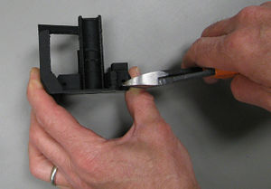
Snipping out z-axis zero adjustment support.With a pair of diagonal cutters, snip out the support between the z-axis zero adjustment screw opening and tab on the motor end.
With a 3mm drill bit, ream the holes in the ends of the motor end guide rod openings, motor mount screw holes and open the hole for the z-axis zero adjustment screw. This last part can be time consuming and care must be taken to not break off the z-axis zero adjustment tab.
On the idler end, ream the holes for the guide rod retainers with a 3mm drill bit.
Ream the 3mm hole in the end stop holder with a 3mm drill bit. Use the tip of the drill bit to chamfer the small holes for the limit switch but do not ream the small holes out. Thread the holes by turning the M2 x 10mm screws into them.
Ream the set screw holes on the pulley with a 3mm drill bit. Ream the pulley shaft hole with a 5mm drill bit. If necessary, clean out set screw nut slots with a sharp knife. Insert the set screw nuts, pushing all the way to the bottom of the nut traps. The x-axis pulley uses M3 x 10mm cap screws for set screws. Start the set screws but do not let them extend into the shaft opening.
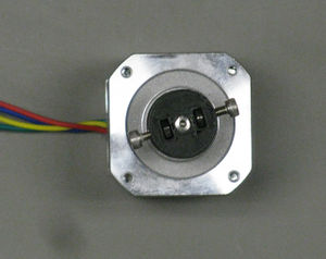
Pulley on motor.When on the motor shaft, the pulley is oriented such that the set screws are farthest from the motor. With the shaft up and the set screws up, align one set screw with the flat on the motor shaft and push the pulley onto the shaft. If necessary, use a 13mm wrench as a pusher, flat side on the pulley face.
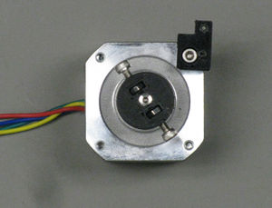
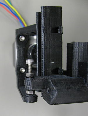
End stop holder on motor.Attach the end stop holder to one corner of the stepper motor with M3 x 10mm screw. The end stop holder should go on the top, right corner with the motor leads to your left.
Attach the stepper motor to the motor end with three M3 x 10mm screws.
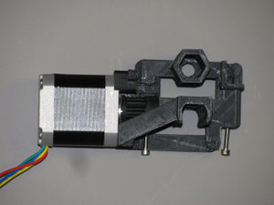
Motor end with motor and guide rod adjustment screws.Drop an M3 nut into one guide rod opening in the motor end. With an 8mm smooth rod, push the nut all the way to the end of the opening with hopes that it will fall into the M3 nut trap printed into the end of the opening. Work with the nut until it sets in the nut trap and then start an M3 x 20mm screw into the nut. Repeat with the remaining guide rod opening.
Z-axis zero-adjustment.Start an M3 nut onto an M3 x 20mm screw and run up the screw about 10mm. Push the screw through the hole z-axis zero adjustment and place another M3 nut on the protruding end. Tighten the latter nut until the nut up on the screw seats into the nut trap in the z-axis zero adjustment. Adjust the screw and nuts such that the tab is slightly bent.
Put M3 x 20mm screws through the guide rod retainer holes in the idler end and finger tighten M3 nuts onto them.
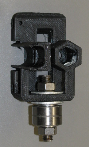
Idler bearing assembly.Push the M8 x 50mm threaded rod into the hole in the idler end and place an M8 fender washer on the interior side followed by an M8 nut. Place the other M8 fender washer on the outside so that the plastic is sandwiched between the two fender washers. Put on an M8 washer, then two 608zz bearings followed by an M8 washer and then an M8 nut. Tighten the entire assembly.
Snap the z-axis LM8UU bearings into their saddles on both the idler and motor ends. Make sure the bearings are fully seated in the saddles - there are spacers in the saddles that the bearings must be between.
Push the 8mm drill rod into the guide rod holes in the motor end and slide an LM8UU bearing onto each guide rod. Push the idler end onto the opposite ends of the drill rod.
Pass one end of the T5 belt through and around the flag-less belt terminator and pull the tail of the belt back through the terminator such that <10mm of tail exits the terminator. With the flagged terminator, make sure that the flag is on the flat side of the belt. See y-axis assembly for pictures.
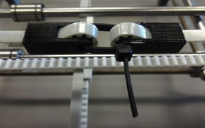
Assembled belt tensioner.Loop the end of the belt having the flagged terminator around the pulley with the flag on the same side as the end stop holder. Loop the other end of the belt around the idler bearings. Pass one end of the large wire tie through the belt terminators and tighten the belt firmly. Snip off the end of the wire tie but leave enough to grip with pliers for future tightening.
Attach the x-axis limit switch to its holder on the x-motor with a pair of M2 x 10mm screws. Ensure that the flag on the belt terminator engages the switch arm (arm should be upwards).