Sophivorus (talk | contribs) m (Text replacement - "{{#widget:YouTube\|id=([^}]+)}}" to "{{Video|$1}}") |
Sophivorus (talk | contribs) m (Rename "affiliations" parameter to "organizations", to unify terminology throughout Appropedia) |
||
| (25 intermediate revisions by 7 users not shown) | |||
| Line 1: | Line 1: | ||
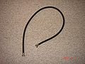
[[File:DSC02139.jpg|thumb|Figure 1: Hand Pump]] | |||
= | {{Project data | ||
| status = Designed, Prototyped | |||
| instance-of = Water pump | |||
| location = Kingston, Canada | |||
}} | |||
In many developing countries, there is an increasing need for affordable water gathering systems. The main system currently used in several developing countries is a hand-operated pump since they are the most sustainable low cost option for safe water supply in resource poor settings. They are used for many purposes, industrial, marine, irrigation, and leisure activities. | |||
< | The hand pump being analyzed in this report is very cheap and easy to make, it can be seen in figure 1 below. It utilizes the water hammer effect to pump water. The water hammer effect is a pressure surge or wave resulting when fluid in motion is forced to stop or change direction suddenly. Water hammer commonly occurs when a valve is closed suddenly at an end of a pipeline system, and a pressure wave propagates in the pipe.<ref>Plast-O-Matic: Valve Info Center, "Water Hammer", http://www.plastomatic.com/water-hammer.html, Accessed March 23, 2010</ref> | ||
== Engineering == | |||
== Functionality == | |||
A diagram of the system can be seen in figure 2 below. When the hose moves down, the foot valve on the end of the garden hose opens allowing the flow of water. When the garden hose moves up, the foot valve on the garden hose closes and more water is pulled into the PVC schedule 40 pipe. | |||
A diagram of the system can be seen in figure 2 below. | |||
<center> | <center> | ||
{| | {| class="wikitable" | ||
!width="140"| | ! width="140"| | ||
|- border=0 | |- border=0 | ||
| [[ | | [[File:functionofthehandpump.jpg|300px|Function of the Hand Pump]] | ||
|} | |} | ||
| Line 40: | Line 30: | ||
== Calculations == | == Calculations == | ||
The density of water at atmospheric conditions is ρ=1000kg/m<sup>3</sup>. | As mentioned earlier this pump utilizes the water hammer effect. In most practical cases, this effect occurs at very high flow rates and pressures so compressibility of the fluid should be considered. For the hand pump being created, incompressibility can be assumed because very low flow rates and pressures are being considered. | ||
The density of water at atmospheric conditions is ρ=1000kg/m<sup>3</sup>. This factor can be used in the calculation of the pressure of the water entering the foot valve at the end of the hose. The pressure of the water entering at the end of the hose, P<sub>1</sub>, can be found using equation (1). | |||
<center> | <center> | ||
[[ | [[File:equation1.jpg|200px|Equation 1]] | ||
</center> | </center> | ||
Where the gravitational constant is g=9.81m/s<sup>2</sup> and the atmospheric pressure is 101,325Pa. | Where the gravitational constant is g=9.81m/s<sup>2</sup> and the atmospheric pressure is 101,325Pa. The velocity of the water entering the pump will be the same as the velocity at which the user propels the hose downward into the well. Assuming in each downward motion the hose travels a distance of 0.15m and this motion takes 0.5 seconds to execute than the velocity at which the hose is moving is 0.3m/s. Therefore the velocity of the water entering the hose is V<sub>1</sub>=0.3m/s. Since compressibility effects can be ignored the Bernoulli equation, equation (2), can be used to calculate the exiting velocity. | ||
<center> | <center> | ||
[[ | [[File:equation2.jpg|300px|Equation 2]] | ||
</center> | </center> | ||
Where h<sub>2</sub>-h<sub>1</sub> is the difference in height between the top and bottom of the hose and this is indicated in figure 3 below. | Where h<sub>2</sub>-h<sub>1</sub> is the difference in height between the top and bottom of the hose and this is indicated in figure 3 below. P<sub>2</sub> can be taken as zero since it is equal to the atmospheric pressure. Note a control volume was taken around the hose and this is indicated in figure 3 below. | ||
<center> | <center> | ||
{| | {| class="wikitable" | ||
!width="140"| | ! width="140"| | ||
|- border=0 | |- border=0 | ||
| [[ | | [[File:demonstrationofflow.jpg|300px|Demonstration of Flow]] | ||
|} | |} | ||
| Line 76: | Line 67: | ||
<center> | <center> | ||
[[ | [[File:equation3.jpg|200px|Equation 3]] | ||
</center> | </center> | ||
Where [[ | Where [[File:equation4.jpg|100px|Equation 4]] | ||
Flow rate for different well lengths can be seen in table 1 below. | Flow rate for different well lengths can be seen in table 1 below. | ||
| Line 86: | Line 77: | ||
<center> | <center> | ||
style="text-align:center; font-weight:bold; background:#CEF2CE;" | style="text-align:center; font-weight:bold; background:#CEF2CE;" | ||
{| class="wikitable | |||
|+Table 1: Flow rates for different well lengths | {| class="wikitable" | ||
|+ Table 1: Flow rates for different well lengths style="text-align:center;" | |||
| style="font-weight:bold; background:#CEF2CE;" | Well Depth (ft) | | style="font-weight:bold; background:#CEF2CE;" | Well Depth (ft) | ||
| 10 | | 10 | ||
| Line 148: | Line 139: | ||
</center> | </center> | ||
= Regional Considerations = | == Regional Considerations == | ||
Community participation in rural water supply is essential for the successful implementation of hand-powered pumps. As the number of hand pumps installed in a country increases the demand for mobile maintenance teams increases also, unless the village assumes responsibility for the maintenance of the hand-pump. For this to occur the hand-pump technology has to be suitable for village maintenance, there has to be a designated and trained caretaker of the pump and there must be spare parts that are readily available. To purchase spare parts the village can set up a cash collection fund and possibly receive backup from the government or other local agencies.<ref name="World Bank">Tschannerl, Gerhard., Bryan, Kedar., Rural Water Supply Handpumps Project, The World Bank, 1984, ISBN 0821306480</ref> | |||
This pump is limited to regions with wells that have deep water levels to allow for the pumping action. | Plastic materials are increasingly used in hand-pump designs because of low costs and corrosion resistance. However, manufacturing processes to make high quality plastic products are often lacking in developing countries.<ref name="World Bank" />This pump is limited to regions with wells that have deep water levels to allow for the pumping action. Water quality plays an important role in water supply from wells. Problems that are frequently encountered are corrosivity (affecting the pump parts and the rising main if made of iron), excess minerals (possibly resulting in a taste that is objectionable to the users), and surface pollution (i.e. organic materials or agriculture chemicals). Where such problems are suspected to exist, the water quality should be appropriately monitored and the design and completion of the wells corrected to avoid problems to the degree possible.<ref name="World Bank" />= Required Materials = | ||
= Required Materials = | |||
Here is a list of the required materials needed to build this pump: | Here is a list of the required materials needed to build this pump: | ||
<gallery> | |||
File:gardenhose.jpg| 1. 5/8" or larger garden hose (inside diameter) | |||
File:adapter.jpg| 2.3/4" garden hose adapter | |||
File:openeyehook.jpg| 3. Open eye-hook, washers and nuts | |||
File:nyloncord.jpg| 4. 1/2" nylon cord | |||
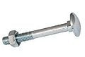
File:carriagebolts.jpg| 5. 1/2" carriage bolts, washer and nuts | |||
File:PVCpipe.jpg| 6. 2" inside diameter PVC schedule 40 pipe<br>7. 1/2" holes in 2" PVC pipe sleeve | |||
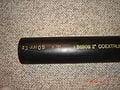
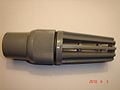
File:footvalve.jpg| 8. 3/4" foot valve | |||
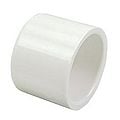
File:pipecap.jpg| 9. 2" PVC schedule 40 pipe cap | |||
</gallery> | |||
If these materials are not available, the following alternative materials can be used: | If these materials are not available, the following alternative materials can be used: | ||
| Line 178: | Line 165: | ||
# Instead of the nylon cord any other rope could be used | # Instead of the nylon cord any other rope could be used | ||
# Any other bolts could be used instead of carriage bolts | # Any other bolts could be used instead of carriage bolts | ||
# Any other | # Any other 2" pipe could be used instead of the PVC schedule 40 pipe | ||
# Any other pipe cap could be used as long as it fits the appropriate pipe being used | # Any other pipe cap could be used as long as it fits the appropriate pipe being used | ||
= Required Tools = | == Required Tools == | ||
Here is a list of the required tools needed to build the pump: | Here is a list of the required tools needed to build the pump: | ||
| Line 194: | Line 182: | ||
# Any other methods could be used to attach the matching cap with the appropriate pipe used in the assembly of this pump | # Any other methods could be used to attach the matching cap with the appropriate pipe used in the assembly of this pump | ||
= Hand Pump Design = | == Hand Pump Design == | ||
== Suggested Design == | == Suggested Design == | ||
Below is a systematic process showing how to build the pump. | Below is a systematic process showing how to build the pump. | ||
{{ | {{Step | ||
| | | number = 1 | ||
|Image: | | text = Glue the 2" PVC schedule 40-pipe cap onto the end of the 2" PVC schedule 40 pipe and let dry | ||
|Image: | | image = Image:glue.jpg | ||
|Image: | | caption = PVC Glue | ||
|Image: | }} | ||
|Image: | |||
|Image: | {{Step | ||
|Image: | | number = 2 | ||
|Image: | | text = Drill twelve 1/2" holes in PVC pipe with 1" spacing<br><br>Note drill holes where arrows are located | ||
|Image: | | image = Image:drill.jpg | ||
| caption = Drill | |||
}} | |||
{{Step | |||
| number = 3 | |||
| text = Fasten PVC schedule 40 pipe to the side of the well casing with 1/2" carriage bolts and nuts | |||
| image = Image:bolts.jpg | |||
| caption = Bolts | |||
}} | |||
{{Step | |||
| number = 4 | |||
| text = Fasten the open eye-hook to the side of the well wall with the washers and nuts | |||
| image = Image:eyehook.jpg | |||
| caption = Eye-Hook | |||
}} | |||
{{Step | |||
| number = 5 | |||
| text = Thread the garden hose on to the 3/4" garden hose adapter | |||
| image = Image:adapterthread.jpg | |||
| caption = Thread Adapter | |||
}} | |||
{{Step | |||
| number = 6 | |||
| text = Thread the 3/4" foot valve onto the 3/4" adapter and garden hose | |||
| image = Image:footvalvethread.jpg | |||
| caption = Thread Foot Valve | |||
}} | |||
{{Step | |||
| number = 7 | |||
| text = Tie the 1/2" nylon rope around the other end of the garden hose | |||
| image = Image:nylonrope1.jpg | |||
| caption = Nylon Rope1 | |||
}} | |||
{{Step | |||
| number = 8 | |||
| text = Tie a loop on the other end of the 1/2" nylon rope | |||
| image = Image:loop.jpg | |||
| caption = Loop | |||
}} | |||
{{Step | |||
| number = 9 | |||
| text = Feed the garden hose down the PVC schedule 40 pipe with the 3/4" foot valve first | |||
| image = Image:feed.jpg | |||
| caption = Feed | |||
}} | |||
{{Step | |||
| number = 10 | |||
| text = Hook the nylon rope onto the open eye-hook to secure the hose to the side of the well wall | |||
| image = Image:secure.jpg | |||
| caption = secure | |||
}} | }} | ||
| Line 216: | Line 262: | ||
== Prototype == | == Prototype == | ||
To test the validity of this pump a prototype was created. | To test the validity of this pump a prototype was created. The materials used include: | ||
<gallery> | |||
File:prubber.jpg| 1. 1/2" rubber hose with a length of 52" | |||
File:PVCpipe.jpg| 2. 2" PVC schedule 40 pipe with a length of 60" | |||
File:Footvalve.jpg| 3. 3/4" foot valve | |||
File:adapter.jpg| 4. 3/4" adapter | |||
</gallery> | |||
The assembled prototype of the pump can be seen in figure 4 below. | The assembled prototype of the pump can be seen in figure 4 below. | ||
<center> | <center> | ||
{| | {| class="wikitable" | ||
!width="140"| | ! width="140"| | ||
|- border=0 | |- border=0 | ||
| [[ | | [[File:assembledprototypeinwater.jpg|300px|Assembled Prototype in Water]] | ||
|} | |} | ||
| Line 240: | Line 284: | ||
</center> | </center> | ||
It is recommended that when using the pump short quick up and down movements are made to pump the water. A video of the hand-powered pump being used can be seen here: | It is recommended that when using the pump short quick up and down movements are made to pump the water. A video of the hand-powered pump being used can be seen here: | ||
<center> | <center> | ||
| Line 249: | Line 293: | ||
</center> | </center> | ||
= Cost Analysis = | == Cost Analysis == | ||
Compared to the traditional hand-pump, this hand-pump is cheap and effective method for gathering water from wells. | Compared to the traditional hand-pump, this hand-pump is cheap and effective method for gathering water from wells. However, the traditional hand-pump can move water at a much faster flow rate. In table 2 below is a cost analysis for the suggested hand-pump design in section 6.1.<ref>Canadian Tire, "Plumbing Parts", http://www.canadiantire.ca/home.jsp?site=WebStore, Accessed March 23, 2010</ref><ref>Home Depot, "Plumbing Parts", http://web.archive.org/web/20150906205127/http://www.homedepot.ca/webapp/wcs/stores/servlet/Home?catalogId=10051&storeId=10051&langId=-15, Accessed March 23, 2010</ref><ref>Northern PVC, "Plumbing Parts", http://web.archive.org/web/20210116091648/http://www.northernpvc.com/, Accessed March 23, 2010</ref> | ||
<center> | <center> | ||
{| class="wikitable | {| class="wikitable" | ||
|+ Table 2: Suggested design cost breakdown | |+ Table 2: Suggested design cost breakdown style="text-align:center; font-weight:bold; background:#CEF2CE;" | ||
| align="center" | Component | | align="center" | Component | ||
| align="center" | Cost | | align="center" | Cost | ||
| Line 301: | Line 344: | ||
| align="center" | $0.89 | | align="center" | $0.89 | ||
| align="center" | Northern PVC | | align="center" | Northern PVC | ||
|} | |} | ||
| Line 312: | Line 354: | ||
'''Table 3: Total cost for different well depths''' | '''Table 3: Total cost for different well depths''' | ||
{| class="wikitable | {| class="wikitable" | ||
|- style="text-align:center; font-weight:bold; background:#CEF2CE;" | |- style="text-align:center; font-weight:bold; background:#CEF2CE;" | ||
| align="center" | Well Depth (ft) | | align="center" | Well Depth (ft) | ||
| Line 331: | Line 373: | ||
| align="center" | 150 | | align="center" | 150 | ||
| align="center" | $359.35 | | align="center" | $359.35 | ||
|} | |} | ||
</center> | </center> | ||
Standard lever hand pumps cost $160 to $300 US depending on the model.<ref> Hand Pump Option in Africa, "Hand Pump", http://www.handpump.org/handpump_option_in_afrika/index.htm, Accessed March 23, 2010 </ref> | Standard lever hand pumps cost $160 to $300 US depending on the model.<ref>Hand Pump Option in Africa, "Hand Pump", http://web.archive.org/web/20120910163742/http://www.handpump.org:80/handpump_option_in_afrika/index.htm, Accessed March 23, 2010</ref> Therefore, this pump should only be implemented with depths less than 100ft. For depths greater than 100ft the standard lever hand pump should be implemented. | ||
= References = | == References == | ||
<references /> | |||
{{Page data | |||
| part-of = Mech425 | |||
| organizations = Queen's University | |||
| keywords = Engineering, Water | |||
}} | |||
[[Category:Appropriate technology videos]] | [[Category:Appropriate technology videos]] | ||
[[Category:Engineering videos]] | [[Category:Engineering videos]] | ||
[[Category:Water videos]] | [[Category:Water videos]] | ||
[[Category:Engineering]] | |||
[[Category:Water]] | |||
Latest revision as of 18:13, 29 January 2024

In many developing countries, there is an increasing need for affordable water gathering systems. The main system currently used in several developing countries is a hand-operated pump since they are the most sustainable low cost option for safe water supply in resource poor settings. They are used for many purposes, industrial, marine, irrigation, and leisure activities.
The hand pump being analyzed in this report is very cheap and easy to make, it can be seen in figure 1 below. It utilizes the water hammer effect to pump water. The water hammer effect is a pressure surge or wave resulting when fluid in motion is forced to stop or change direction suddenly. Water hammer commonly occurs when a valve is closed suddenly at an end of a pipeline system, and a pressure wave propagates in the pipe.[1]
Engineering[edit | edit source]
Functionality[edit | edit source]
A diagram of the system can be seen in figure 2 below. When the hose moves down, the foot valve on the end of the garden hose opens allowing the flow of water. When the garden hose moves up, the foot valve on the garden hose closes and more water is pulled into the PVC schedule 40 pipe.

|
Figure 2: Function of the hand pump
Calculations[edit | edit source]
As mentioned earlier this pump utilizes the water hammer effect. In most practical cases, this effect occurs at very high flow rates and pressures so compressibility of the fluid should be considered. For the hand pump being created, incompressibility can be assumed because very low flow rates and pressures are being considered.
The density of water at atmospheric conditions is ρ=1000kg/m3. This factor can be used in the calculation of the pressure of the water entering the foot valve at the end of the hose. The pressure of the water entering at the end of the hose, P1, can be found using equation (1).

Where the gravitational constant is g=9.81m/s2 and the atmospheric pressure is 101,325Pa. The velocity of the water entering the pump will be the same as the velocity at which the user propels the hose downward into the well. Assuming in each downward motion the hose travels a distance of 0.15m and this motion takes 0.5 seconds to execute than the velocity at which the hose is moving is 0.3m/s. Therefore the velocity of the water entering the hose is V1=0.3m/s. Since compressibility effects can be ignored the Bernoulli equation, equation (2), can be used to calculate the exiting velocity.

Where h2-h1 is the difference in height between the top and bottom of the hose and this is indicated in figure 3 below. P2 can be taken as zero since it is equal to the atmospheric pressure. Note a control volume was taken around the hose and this is indicated in figure 3 below.

|
Figure 3: Demonstration of flow
Using the exiting velocity, V2, the volumetric flow rate of the system can be found with equation (3).

Where ![]()
Flow rate for different well lengths can be seen in table 1 below.
style="text-align:center; font-weight:bold; background:#CEF2CE;"
| Well Depth (ft) | 10 | 20 | 50 | 100 | 150 |
| Density of Water (kg/m3) | 1,000 | 1,000 | 1,000 | 1,000 | 1,000 |
| Gravity (m/s2) | 9.81 | 9.81 | 9.81 | 9.81 | 9.81 |
| Atmospheric Pressure (Pa) | 101,325 | 101,325 | 101,325 | 101,325 | 101,325 |
| Pressure at Intake (Pa) | 131,226 | 161,127 | 250,829 | 400,334 | 549,838 |
| Exiting Velocity (m/s) | 5.50 | 7.76 | 12.25 | 17.32 | 21.21 |
| Exiting Area (m2) | 0.000198 | 0.000198 | 0.000198 | 0.000198 | 0.000198 |
| Volumetric Flow Rate (m3/s) | 0.001089 | 0.001536 | 0.002425 | 0.003428 | 0.004197 |
Regional Considerations[edit | edit source]
Community participation in rural water supply is essential for the successful implementation of hand-powered pumps. As the number of hand pumps installed in a country increases the demand for mobile maintenance teams increases also, unless the village assumes responsibility for the maintenance of the hand-pump. For this to occur the hand-pump technology has to be suitable for village maintenance, there has to be a designated and trained caretaker of the pump and there must be spare parts that are readily available. To purchase spare parts the village can set up a cash collection fund and possibly receive backup from the government or other local agencies.[2]
Plastic materials are increasingly used in hand-pump designs because of low costs and corrosion resistance. However, manufacturing processes to make high quality plastic products are often lacking in developing countries.[2]This pump is limited to regions with wells that have deep water levels to allow for the pumping action. Water quality plays an important role in water supply from wells. Problems that are frequently encountered are corrosivity (affecting the pump parts and the rising main if made of iron), excess minerals (possibly resulting in a taste that is objectionable to the users), and surface pollution (i.e. organic materials or agriculture chemicals). Where such problems are suspected to exist, the water quality should be appropriately monitored and the design and completion of the wells corrected to avoid problems to the degree possible.[2]= Required Materials =
Here is a list of the required materials needed to build this pump:
-
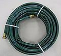
1. 5/8" or larger garden hose (inside diameter)
-
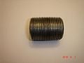
2.3/4" garden hose adapter
-
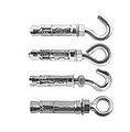
3. Open eye-hook, washers and nuts
-
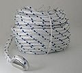
4. 1/2" nylon cord
-
5. 1/2" carriage bolts, washer and nuts
-
6. 2" inside diameter PVC schedule 40 pipe
7. 1/2" holes in 2" PVC pipe sleeve -
8. 3/4" foot valve
-
9. 2" PVC schedule 40 pipe cap


If these materials are not available, the following alternative materials can be used:
- Instead of a garden hose any hose of similar size can be used
- Instead of an adapter any other method for attaching the foot valve to the hose can be used as long as an appropriate seal is made between the two
- Any other hook can be used as opposed to the open eye-hook
- Instead of the nylon cord any other rope could be used
- Any other bolts could be used instead of carriage bolts
- Any other 2" pipe could be used instead of the PVC schedule 40 pipe
- Any other pipe cap could be used as long as it fits the appropriate pipe being used
Required Tools[edit | edit source]
Here is a list of the required tools needed to build the pump:
- Drill and drill bits
- Pipe tape or compound to provide tight seal
- PVC solvent or glue to attach pipe cap
Alternative tools:
- Any other device that can drill the appropriate size holes could be used
- Any other sealing glues or solvents could be used to match the appropriate hose and pipe used
- Any other methods could be used to attach the matching cap with the appropriate pipe used in the assembly of this pump
Hand Pump Design[edit | edit source]
Suggested Design[edit | edit source]
Below is a systematic process showing how to build the pump.

Glue the 2" PVC schedule 40-pipe cap onto the end of the 2" PVC schedule 40 pipe and let dry

Drill twelve 1/2" holes in PVC pipe with 1" spacing
Note drill holes where arrows are located

Fasten PVC schedule 40 pipe to the side of the well casing with 1/2" carriage bolts and nuts

Fasten the open eye-hook to the side of the well wall with the washers and nuts

Thread the garden hose on to the 3/4" garden hose adapter

Thread the 3/4" foot valve onto the 3/4" adapter and garden hose

Tie the 1/2" nylon rope around the other end of the garden hose

Tie a loop on the other end of the 1/2" nylon rope

Feed the garden hose down the PVC schedule 40 pipe with the 3/4" foot valve first

Hook the nylon rope onto the open eye-hook to secure the hose to the side of the well wall
Note the hose length may have to be adjusted to fit the well depth. For the appropriate length hose, the foot valve should be just above the well cap when hanging from the open eye-hook as seen in step 10 above.
Prototype[edit | edit source]
To test the validity of this pump a prototype was created. The materials used include:
-
1. 1/2" rubber hose with a length of 52"
-
2. 2" PVC schedule 40 pipe with a length of 60"
-
3. 3/4" foot valve
-
4. 3/4" adapter

The assembled prototype of the pump can be seen in figure 4 below.

|
Figure 4: Assembled prototype in water
It is recommended that when using the pump short quick up and down movements are made to pump the water. A video of the hand-powered pump being used can be seen here:

Cost Analysis[edit | edit source]
Compared to the traditional hand-pump, this hand-pump is cheap and effective method for gathering water from wells. However, the traditional hand-pump can move water at a much faster flow rate. In table 2 below is a cost analysis for the suggested hand-pump design in section 6.1.[3][4][5]
| Component | Cost | Distributor |
| 5/8" Garden Hose Adapter | $0.49/foot | Home Depot |
| 3/4" Garden Hose Adapter | $2.00 | Canadian Tire |
| 1/2" Open Eye-Hook | $1.00 | Canadian Tire |
| 1/2" Nylon Chord | $2.39 | Canadian Tire |
| 1/2" Carriage Bolts | $2.00 | Home Depot |
| 1/2" Washer | $0.05 | Canadian Tire |
| 1/2" Nut | $0.05 | Canadian Tire |
| 2" PVC Schedule 40 Pipe | $1.75/foot | Canadian Tire |
| 3/4" Foot Valve | $9.99 | Canadian Tire |
| 2" PVC Schedule 40 Pipe Cap | $0.89 | Northern PVC |
For the systems specified in table 1, the total cost of components are listed in table 3 below.
Table 3: Total cost for different well depths
| Well Depth (ft) | Cost |
| 10 | $45.75 |
| 20 | $68.15 |
| 50 | $135.35 |
| 100 | $247.35 |
| 150 | $359.35 |
Standard lever hand pumps cost $160 to $300 US depending on the model.[6] Therefore, this pump should only be implemented with depths less than 100ft. For depths greater than 100ft the standard lever hand pump should be implemented.
References[edit | edit source]
- ↑ Plast-O-Matic: Valve Info Center, "Water Hammer", http://www.plastomatic.com/water-hammer.html, Accessed March 23, 2010
- ↑ 2.0 2.1 2.2 Tschannerl, Gerhard., Bryan, Kedar., Rural Water Supply Handpumps Project, The World Bank, 1984, ISBN 0821306480
- ↑ Canadian Tire, "Plumbing Parts", http://www.canadiantire.ca/home.jsp?site=WebStore, Accessed March 23, 2010
- ↑ Home Depot, "Plumbing Parts", http://web.archive.org/web/20150906205127/http://www.homedepot.ca/webapp/wcs/stores/servlet/Home?catalogId=10051&storeId=10051&langId=-15, Accessed March 23, 2010
- ↑ Northern PVC, "Plumbing Parts", http://web.archive.org/web/20210116091648/http://www.northernpvc.com/, Accessed March 23, 2010
- ↑ Hand Pump Option in Africa, "Hand Pump", http://web.archive.org/web/20120910163742/http://www.handpump.org:80/handpump_option_in_afrika/index.htm, Accessed March 23, 2010