
- Flowmeters are the devices that are used to measure the flow of liquid & gases that pass through them.
- Flowmeter that measure the flow by calculating the amount of liquid flown in unit time are called velocity flowmeter. This type of flowmeter typically provides with velocity of flow (ex: 10 litres per minute).
- Volumetric flowmeter on the other hand measure the total amount that has been discharged. For example this flowmeters may be utilized to know the amount used in house over a month(100 l).
- This project is focused to have a flowmeter that has the ability to act both as velocity flowmeter & volumetric flowmeter. So, that it can be used by researchers and also customizable to their requirement rather than procuring a new one for different applications.
- A typical flow meter has a casing, transducer and transmitter. Casing is to ensure leak proof operation thereby avoiding any measurement error. Transducer senses the fluid passing through them and converted through transmitter into raw signal. In this project, the data is processed using Arduino and displayed through LCD display.
Bill of Materials[edit | edit source]
- Component of 3-d printer Casing:
- Lower casing with integrated input and output tube
- Blade rotor
- Bearing carrying plate
- Magnet mounted plate
- top casing cover
- Bearing (outer dia 30, inner dia 10, thickness 10) (in mm)
- 2XM8 bolt and nut

- Electrical Component
- Auduino Board
- Couple of breadboard
- Hall effect sensor
- LCD display
- Electrical wires
- All parts required for the assembly of the apparatus available at https://www.youmagine.com/designs/flow-meter
Tools needed for fabrication of flowmeter[edit | edit source]
- MOST Delta RepRap or similar RepRap 3-D printer
Skills and Knowledge Necessary to edit design[edit | edit source]
- 3D Modelling software - FreeCAD
- CURA(Matter control software)
- Arduino programming
Arduino board and hall effect sensor[edit | edit source]
Arduino is a open source hardware and software company that manufactures Arduino. Arduino is a micro controller,for projects requiring less computational memory this is a very useful device. ARduino image is shown below

In our project we have used arduino to compute flow. For detecting flow we are using hall effect sensor.


Hall effect sensor works on the principle of magnetic field. It has a thin strip of metal which is given a potential difference across it. Whenever there is magnetic field, the metal strip deflects causing a change in output voltage. the change in voltage output is detected as pulse on arduino. Unlike other transducer hall effect has an advantage, it detects static magnetic field as well ; while other sensor detects change in magnetic field. Over period of time hall effect sensor has found its uses increasingly in varied application viz as an encoder,proximity sensor, rpm, limit switch. Here in our project Hall effect sensor works as a encoder. It has three terminal two for supply and the third one is for signal. The working of hall effect sensor is shown in fig and the image of hall effect sensor
Here in our flow meter there is a small button magnet mounted on top of the disk which rotates with the bearing.The magnet is detected by hall effect sensor whenever it crosses the near field. This acts as digital input on arduino. The no of pulses is used to compute the rate of flow and total flow as well. Computing the no of pulses within a sampling period gives the rate of flow.
For displaying flow we are using 16x2 LCD display, mounted on bread board. The arrangement is as shown in the figure. We are using pin no 10 of arduino for hall effect signal
Ardunio code[edit | edit source]
Detection of magnet by hall effect sensor is used as count in the program, the program sums this count with the previous counts stored in a variable ; multiplying with a calibration factor gives the flow. In future works the setting of calibration will be made user input This flow is displayed on the LCD. Arduino code is as follows
include <LiquidCrystal.h>
const int buttonPin = 10 ; // the pin that the pushbutton is attached to
const int ledPin = 13; // the pin that the LED is attached to
const int rs = 8, en = 9, d4 = 4, d5 = 5, d6 = 6, d7 = 7;
LiquidCrystal lcd(rs, en, d4, d5, d6, d7);
// Variables will change:
int buttonPushCounter = 0;
int buttonState = 0;
int lastButtonState = 0;
int Calc;
int Calc1;
int Calc_lst=0;
void setup() {
// initialize the button pin as a input:
pinMode(ledPin, OUTPUT);
// initialize serial communication:
Serial.begin(9600);
lcd.begin(16, 2);
}
void loop() {
buttonState = digitalRead(buttonPin);
// compare the buttonState to its previous state
if (buttonState != lastButtonState) {
// if the state has changed, increment the counter
if (buttonState == HIGH) {
// if the current state is HIGH then the button went from off to on:
buttonPushCounter++;
Serial.println("on");
Serial.print("number of button pushes: ");
Serial.println(buttonPushCounter);
} else {
// if the current state is LOW then the button went from on to off:
Serial.println("off");
}
delay(5);
}
lastButtonState = buttonState;
if (buttonPushCounter == 0) {
digitalWrite(ledPin, HIGH);
} else {
digitalWrite(ledPin, LOW);
}
lcd.clear();
lcd.setCursor(0,0);
Calc= buttonPushCounter*50;
lcd.print("Total counts ");
lcd.print(buttonPushCounter);
lcd.setCursor(0,1);
lcd.print("Total flow ");
lcd.print(Calc);
lcd.print(" mL");
delay(2);
}
Technical Specifications and Assembly Instructions[edit | edit source]
- Download all the.stl files from the link mentioned above.
- Print all the parts keeping equal scale(x=100% y=100% z=100%) on CURA.
- Trim off any extruding flash obstructing assembly.
- Take the lower casing and on it place the blade rotor, the grove part of the blade should go on the casing.
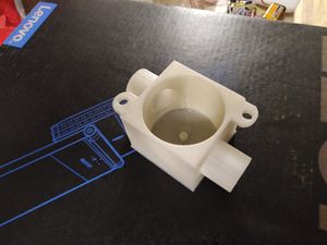
Lower casing 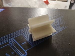
Blade - Smaller hole is designed and hence material has to be scraped form the inner surface of the printed part. Ensure sealing of bearing for any leak. Take the bearing assembled and bolt it to the lower casing and on it place the blade rotor, the grove part of the blade should go on the casing.
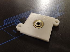
Bearing plate - Place the magnet mounted plate on the other side of bearing. Place the covering on it top and bolt the whole assembly with M8 bolt and nut
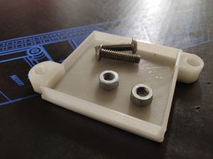
Top Plate - The print time for the complete assembly must be around 12-14 hours with 30% Infill.


- Hall effect sensor is mounted on the casing taking care the diameter of the magnet plate.
- Circuit Connection:
- Hall effect sensor has 3 wires, the two outer for voltage input and the middle wire gives the signal which is straight away given to Arduino.
- The ports of LCD and arduino board are connected as shown in the picture.
- Battery was connected to Arduino board

- Demonstration video as shown
| 3D printed Flowmeter demonstration video |
|---|
Calibration[edit | edit source]
- The component were assembled and was feed into a tap as shown in demonstration. Time was also being recorded. water was allowed to be flow and collected in a bucket. After one minute the water calculated was recorded in litres. The total pulse was noted from LCD display.
- Each pulse reading could consequently be calculated both for litre discharge per min and each pulse computes the flow in each count
- For our case, each pulse was 50 ml of water.
Cost savings[edit | edit source]
- The estimated cost of PLA material is approximately $7 for the basic PLA filament.
- Commercial equivalent costs approximately $50-150. Check the commercial version here -> [1]
- Savings of $90 is easily possible for our apparatus.
- Therefore labs requiring flow meter precisely for very specific use,this device would be very useful. Also with the feature to set calibration by user this device will be used even for liquid with different viscosity
Improvement and adaptability[edit | edit source]
- The no blades of the fan can be modified according to the type of liquid used to be detected by flow meter. Since flow meter with higher mass will require lesser no of blades. And the flowmeter with lower mass will require more no of blades for accuracy
- For better precision the fan shape can be changed to the one shown in the figure. As its blade has curve assisting flow in a particular. Thus reducing error of missing counts while computing flow

- Disadvantage is that it will assist flow in one direction and resist in other direction. If the direction of flow is constant this design will be and improvement
- Flow can be more efficiently been computed with sensor like magnetic coil. There will be a magnetic field across the pipe and change in magnetic field with the flow of liquid will lead to change in output of the sensor. Although efficient but this device is bulky and more used in industrial application
- Since sensor output needs not to be constant. Here the range of operation of hall effect sensor was in acceptable range of arduino specs,so it didn't needed re scaling. For operation outside the range of specs we will have to use an OPAM(operational amplifier) to scale it to different range. For eg some flowmeter are used to open/close valves,valves will require additional voltage ; essentially halleffect sensor with OPAM will be handy in such situation
Future Works[edit | edit source]
- Improvement in design and customizer feature.
- Tolerances of 3d part could be defined for easy assembly.
- Use of cheaper board or customized board for cost reduction.
- Cabinet design for electronic parts.
- Designing and developing similar project for better utilization of electrical component and increasing features.