Background
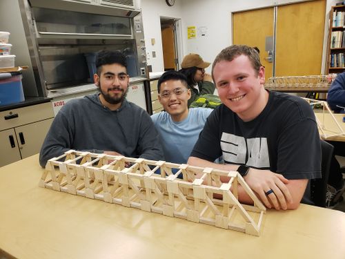
As a part of the Engineering 210 course at Humboldt State University, students were tasked to work in groups of 3 or 4 to build a truss bridge out of balsa wood and super glue. Our group included David Topete, Kong Vang, and Andrew Kizer (listed left to right in Figure 1) and we are the KAD Group. This page is designed to showcase the bridge we built including the design, how it was made, and how it performed.
Project goals
The class project had specific requirements and parameters that each bridge must follow for both design and building:
- The bridge must span 36 in and rest between 2 surfaces with a 1/2 overlay on either side.
- The bridge must have a minimum height of 4 in
- The bridge must have a minimum width of 4 in
- The bridge must support a minimum weight of 24 lbs
- The bridge must be made of balsa wood and super glue only.
Prototype 1
Our design was modeled after a typical Howe Bridge design utilizing right triangles that mirrored over the center. However, prototyping of this design was required to understand the best way to build the bridge and utilize our resources most efficiently.

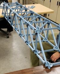
- Our first prototype was made of plastic members, small plastic plates to connect the joints, and metal screws to hold everything together. The purpose of this prototype was to test the construction of the Howe design on an actual scale of the project (see Figure 2). Although our with the materials being used, getting an exact scale model was not possible due to the members being longer than the desired height and width.

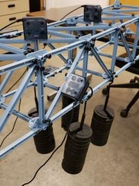
- Our first prototype also allowed the testing of how forces would be applied to the bridge (see Figure 3). By applying weights to the center of the bridge and using sensors along various members close to the weights, we were able to determine which members would be taking the most force and thus allowed us to adjust our design to reinforce those members. While prototyping, it was found that the cross members along the top and bottom of the bridge took very little force compared to most of the side members.
Prototype 2

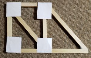
Our second prototype was created to practice cutting the necessary angles for each diagonal member and to test the best types of cuts. This prototype helped us determine the two sided cuts needed to align all the center lines of each member to add extra reinforcement in the joints.
Design

The final dimensions of the bridge were 36" by 5" by 5". Our bridge was focused on reinforcing the joints in order to maximize the load it would hold before failure. To accomplish this, we used a joint design utilized 1/2" by 1/2" balsa wood for the side members, 1/4" by 1/4" balsa wood for the cross members, and 1/8" by 3" balsa wood for the gusset plates along the side and top of the bridge.
How to Build
- Sample gallery
-
Sample caption text.
-
More sample caption text. This would look better with different images. :)
-
Even more sample caption text.
Costs
You may describe your costs here.
| header 1 | header 2 | header 3 |
|---|---|---|
| row 1, cell 1 | row 1, cell 2 | row 1, cell 3 |
| row 2, cell 1 | row 2, cell 2 | row 2, cell 3 |
See Help:Tables and Help:Table examples for more.
