!!This page is under construction!![edit | edit source]
Electron-beam (e-beam) thin-film deposition can be broadly classified as either physical vapor deposition (PVD) or chemical vapor deposition (CVD) method. With PVD, deposition rates are generally lower and the process is carried out at low substrate temperatures. CVD is a high temperature process and deposition rates higher than those characteristic of PVD can be achieved.
Background on E-beam deposition[edit | edit source]
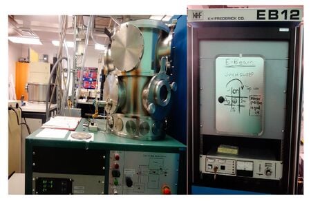
Equipment[edit | edit source]
| E-Beam Model Frederick |
|---|
 |
E-Beam Deposition Frederick Specifications[edit | edit source]
Hardware Description
Electron Beam (E-Beam) Evaporation System Operating Procedure and General Information[edit | edit source]
Microfabrication Facility Michigan Tech Bill Knudsen, Director, wknudsen@mtu.edu
Load Sample(s)[edit | edit source]
- The chamber should be pumped down when you arrive. If not, contact Bill.
- To open the chamber:
a) Close the Gate Valve and wait for ~10 seconds.
b) Open the Vent Valve and wait for A to level off (usually somewhere around 7.6 +2).
c) Close the Vent Valve and wait for ~5 seconds.
d) Press Lift (green button) to open the lid of the chamber.
- After the chamber is open:
a) Put on gloves and lift the sample holder (metal circle) out of the scaffold.
b) Use an Allen Wrench to loosen the screws and clamps.
c) Slide your sample (side to have film facing "up") under one of the clamps. Use the Allen Wrench to tighten the clamp to the sample. Be careful not to clamp too tightly if your sample is brittle! NOTE: Only the part of your sample exposed (outside of the clamp) will have a film after the evaporation is completed.
d) Add film material (Al, In, Cr, or Au) to the crucible, if necessary.
e) Make sure the evaporation chamber is located at the specified film material.
f) Check to see that the Shutter is closed. If the shutter is not closed, press in the shutter knob and turn to the "close" position. Make sure it is completely closed before the sample is loaded.
g) Place the sample holder (sample facing "down") back in the scaffold.
- To close the chamber:
a) Press Motor Down (green button) to lower the lid of the chamber.
b) Once the lid is closed, make sure it is centered on top of the chamber. The lid can be adjusted manually if it is not centered.
c) Open the viewing window to check if the plastic was coated by the last user. The plastic must be transparent in order to run the evaporation successfully. Close the viewing window after check and/or replacement.
- Set vacuum environment:
a) Do NOT set vacuum until the lid and viewing window are closed! b) Open Roughing Valve until A reaches 3 -2. c) Close Roughing Valve and wait for ~5 seconds. d) Open Gate Valve and wait ~1 day.
Evaporate Film[edit | edit source]
- Turn IG2 Button off.
- Turn High Voltage (Control Panel) on with tweezers. The kV will increase. Amps will stay the same.
- Using the unit next to the chamber, increase the Current with the dial.
- Once the spot is visible in the chamber, use the X and Y sliders on the unit to adjust the beam to the center of the crucible.
- Increase the current until a purple glow appears above the crucible. The crucible will also likely be red hot when the glow is apparent. You are ready to evaporate—get a stopwatch!
- Open the Shutter by pressing in the shutter knob and turning to "open".
- Begin timing and wait for the desired time to elapse.
- Decrease Current to "0".
- Turn off High Voltage by pressing the "OFF" button (Control Panel).
10. Close the Shutter by pressing in the shutter knob and turning to "close".
11. To retrieve the sample, open the chamber. (See Load Sample, Step 2.)
Shut Down[edit | edit source]
- Load the new sample (or leave the sample holder empty) and follow the Load Sample section, Steps 1-5 (above).
- Make sure the vacuum is set properly before you leave.
- Log the information into the logbook.
- Clean the work area.
If you have any problems or questions, contact Bill.
General Information[edit | edit source]
Each film material behaves differently in the evaporation system. Trials have been completed to plot film thickness as a function of time for aluminum.
The y-error bars indicate all of the data falls within the required range for a linear trend. The linear trend is further justified when thickness is plotted on a logarithmic scale.
The raw and averaged data are:
Time (s) Thickness (nm) 0 0 12 16.657 12 12.665 12 12.734 58 208.62 58 193.82 58 202.98 58 194.93 60 202.23 60 201.43 60 223.82 60 218.2 120 2340 120 4198 120 3614 300 4130 300 5720 600 14000
Time (s) Average Thickness (nm) 12 14.019 58 201.8067 60 211.42 120 3384 300 4925 600 14000
The film thicknesses were measured on the FE-SEM (thick films) or AFM (thin films).

