Devon Smith (talk | contribs) |
Devon Smith (talk | contribs) |
||
| (15 intermediate revisions by the same user not shown) | |||
| Line 8: | Line 8: | ||
==Abstract== | ==Abstract== | ||
* A dial indicator is a tool used to measure linear displacements. It accomplishes so via the use of a plunger that's constricted to a measured linear movement. Simply, when the plunger is pushed into the body of the tool, the distance it is pushed in is "indicated" on the "dial" face of the tool. This is useful for any kind of precise measurement of thickness, depth, width, and can even be used to ensure a machining device or tool is accurately trammed. | |||
* https://www.youmagine.com/designs/dial-indicator [[Image:Dial Indicator Front.jpg|200px|right]] | |||
* OSAT: http://www.appropedia.org/Open_Source_Appropriate_Technology | |||
== Bill of Materials== | == Bill of Materials== | ||
| Line 37: | Line 39: | ||
|- | |- | ||
| Spacer | | Spacer | ||
| | | 2 | ||
| [https://www.youmagine.com/designs/dial-indicator/ Youmagine] | | [https://www.youmagine.com/designs/dial-indicator/ Youmagine] | ||
| Using PLA | | Using PLA | ||
| Line 90: | Line 92: | ||
== Tools needed for fabrication of the OSAT== | == Tools needed for fabrication of the OSAT== | ||
# [[Athena Build Overview| MOST Delta RepRap]] or similar RepRap 3-D printer | # [[Athena Build Overview| MOST Delta RepRap]] or similar RepRap 3-D printer | ||
# | # Number 2 Phillip's Head Screw Driver | ||
# | # 1/4 inch Open End Wrench | ||
TOOL REQUIREMENTS MAY VARY BASED ON NUT & BOLT SELECTION | TOOL REQUIREMENTS MAY VARY BASED ON NUT & BOLT SELECTION | ||
| Line 101: | Line 103: | ||
== Technical Specifications and Assembly Instructions== | == Technical Specifications and Assembly Instructions== | ||
* Download and print the plastic components listed in the bill of materials | |||
* Recommended: | ** Recommended: | ||
*** Material: PLA | |||
*** Layer Height: 0.25 mm | |||
*** Shell Thickness: 0.8 mm | |||
*** Fill Density: 100% | |||
*** Print Speed: 50 mm/s | |||
*** Printing Temperature: 215 C | |||
* Clean burrs and excess plastic from parts that may be remaining from print | |||
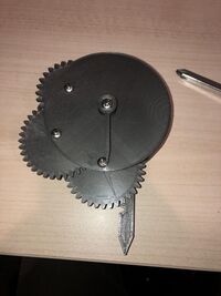
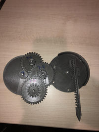
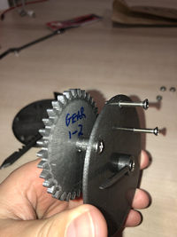
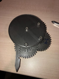
* Align the corresponding components from the bill of materials to the pictures posted below while ensuring: | |||
** All holes align | |||
** All gears mesh together | |||
[[Image:Open Gears.jpg|200px]] | |||
[[Image:SpacerAlignment.jpg|200px]] | |||
[[Image:Rear.jpg|200px]] | |||
[[Image:Dial Indicator Front.jpg|200px]] | |||
* Assemble Fasteners so that the head of the screws are on the face of the indicator | |||
* Lightly tighten fasteners so that gears spin freely with minimal slop | |||
* Assemble needle so that needle is spaced away from dial face | |||
* Once completed, use a protractor to mark the face of the indicator in whichever scale is desired | |||
== Common Problems and Solutions== | == Common Problems and Solutions== | ||
* | * If the gears don't align and interface properly, first ensure they are oriented with the proper gear in the proper location and proper orientation. Also ensure the layering of the gears is correct and in order. Another possibility is that the holes within the body and top components aren't lined up correctly. | ||
* If the plunger is difficult to move: The indicator works best when the dial is rotated to move the plunger to it's location rather than using the plunger to rotate the high gear ratio. | |||
== Cost savings== | == Cost savings== | ||
* | * 87g of PLA ($1.57 USD) + Hardware ($1.58 USD) = '''$3.15 USD Total''' | ||
* current one on the market: | * current one on the market: ($172.80 USD:https://www.mscdirect.com/browse/tnpla/86427457?cid=ppc-google-New+-+Measuring+%26+Inspecting+-+PLA_sW2Cu6rhf___164110844316_c_S&mkwid=sW2Cu6rhf%7Cdc&pcrid=164110844316&rd=k&product_id=86427457&gclid=EAIaIQobChMIyMap7rKV3wIVDAtpCh07fwOtEAQYBCABEgL5M_D_BwE/Current Market Indicator) | ||
* '''Cost savings of $ USD (% cost | * '''Cost savings of $169.65 USD (1.82% of the cost)''' | ||
== Benefited Internet Communities == | == Benefited Internet Communities == | ||
'''Name and add links to at least 5 using single brackets around [url name]:''' | '''Name and add links to at least 5 using single brackets around [url name]:''' | ||
*[http://www.appropedia.org/777_OSAT_projects_2018 Appropedia OSAT Project for MY4777] | *[http://www.appropedia.org/777_OSAT_projects_2018 Appropedia OSAT Project for MY4777] | ||
*[https:// | *[https://grabcad.com/ Grab Cad] | ||
*[https:// | *[https://www.practicalmachinist.com/ Practical Machinist] | ||
*[https://github.com/ Gitbug] | *[https://github.com/ Gitbug] | ||
*[https://www.thingiverse.com/ Thingiverse] | *[https://www.thingiverse.com/ Thingiverse] | ||
| Line 132: | Line 144: | ||
==References== | ==References== | ||
* | * https://www.thingiverse.com/thing:873948/comments | ||
Revision as of 14:53, 10 December 2018
Dial Indicator
Project developed by User:Devon Smith
Template:Statusboxtop Template:Status-design Template:Status-prototype You can help Appropedia by contributing to the next step in this OSAT's status. Template:Boxbottom
Abstract
- A dial indicator is a tool used to measure linear displacements. It accomplishes so via the use of a plunger that's constricted to a measured linear movement. Simply, when the plunger is pushed into the body of the tool, the distance it is pushed in is "indicated" on the "dial" face of the tool. This is useful for any kind of precise measurement of thickness, depth, width, and can even be used to ensure a machining device or tool is accurately trammed.
Bill of Materials
| Part | Quantity | Source | Comments |
|---|---|---|---|
| PLA | ~87 grams | Filament supplier of choice | Color of choice |
| Dial Indicator Body | 1 | Youmagine | Using PLA |
| Dial Indicator Top | 1 | Youmagine | Using PLA |
| Spacer | 2 | Youmagine | Using PLA |
| Dial Indicator Needle | 1 | Youmagine | Using PLA |
| Gear 1-2 | 1 | Youmagine | Using PLA |
| Gear 3-4 | 1 | Youmagine | Using PLA |
| Gear 5-6 | 1 | Youmagine | Using PLA |
| Dial Indicator Plunger | 1 | Youmagine | Using PLA |
| Gear 7 | 1 | Youmagine | Using PLA |
| 6-32 Button Head Cap Screw 1 inch long | 3 | ||
| 6-32 Button Head Cap Screw 1.25 inch long | 1 | ||
| 6-32 Nylock Nut | 4 |
Tools needed for fabrication of the OSAT
- MOST Delta RepRap or similar RepRap 3-D printer
- Number 2 Phillip's Head Screw Driver
- 1/4 inch Open End Wrench
TOOL REQUIREMENTS MAY VARY BASED ON NUT & BOLT SELECTION
Skills and Knowledge Necessary to Make the OSAT
- 3D Printing Knowledge & Capabilities
- Understand the needs & application for a dial indicator
- Ability to assemble fasteners and critically aligned plastic components
Technical Specifications and Assembly Instructions
- Download and print the plastic components listed in the bill of materials
- Recommended:
- Material: PLA
- Layer Height: 0.25 mm
- Shell Thickness: 0.8 mm
- Fill Density: 100%
- Print Speed: 50 mm/s
- Printing Temperature: 215 C
- Recommended:
- Clean burrs and excess plastic from parts that may be remaining from print
- Align the corresponding components from the bill of materials to the pictures posted below while ensuring:
- All holes align
- All gears mesh together
- Assemble Fasteners so that the head of the screws are on the face of the indicator
- Lightly tighten fasteners so that gears spin freely with minimal slop
- Assemble needle so that needle is spaced away from dial face
- Once completed, use a protractor to mark the face of the indicator in whichever scale is desired
Common Problems and Solutions
- If the gears don't align and interface properly, first ensure they are oriented with the proper gear in the proper location and proper orientation. Also ensure the layering of the gears is correct and in order. Another possibility is that the holes within the body and top components aren't lined up correctly.
- If the plunger is difficult to move: The indicator works best when the dial is rotated to move the plunger to it's location rather than using the plunger to rotate the high gear ratio.
Cost savings
- 87g of PLA ($1.57 USD) + Hardware ($1.58 USD) = $3.15 USD Total
- current one on the market: ($172.80 USD:https://www.mscdirect.com/browse/tnpla/86427457?cid=ppc-google-New+-+Measuring+%26+Inspecting+-+PLA_sW2Cu6rhf___164110844316_c_S&mkwid=sW2Cu6rhf%7Cdc&pcrid=164110844316&rd=k&product_id=86427457&gclid=EAIaIQobChMIyMap7rKV3wIVDAtpCh07fwOtEAQYBCABEgL5M_D_BwE/Current Market Indicator)
- Cost savings of $169.65 USD (1.82% of the cost)
Benefited Internet Communities
Name and add links to at least 5 using single brackets around [url name]:


